| Author |
Message |
dazz
Regular Member

Joined: 15/04/2008
Location: Posts: 78 |
| Posted: 08:55am 21 May 2008 |
 Copy link to clipboard Copy link to clipboard |
 Print this post |
|
Hi All,
SMFIS(Stator Magnetic Flux Immersion System)
This is a control system that raises and lowers the hub onto the stator. The position of the hub is always known and the position can be controlled.
The system basically consists of an electromechanical unit that does the raising/lowering, a whole bunch of sensors and micro-switches and an MCU to control it all.
The MCU is also connected to a PC to display/record data
I started out building it because I wasn't keen on de-cogging my 80 series stator. Mostly because of the work involved, the dust(I'm an asthmatic) and mostly because I would probably stuff it up first time and i only had one stator when i thought of the idea.
So, the initial idea was to have the hub raised off the stator until it starts turning and then lower it onto the stator.
But as I progressed, it occurred to me that there might be some other applications for a system like this.
Firtly there are two manual push buttons for raising and lowering the hub. This means the hub can be detached quickly from the stator in the event of an emergency(like sparks flying from the stator 20ft up a windmill pole)
The next idea is much more time consuming. I started exploring the system as a gust capture device. We live in mountainous terrain and if there is wind, it is gusty, never constant like you might find on the coast.
So thinking about this, I pondered possible problems with gusts. Lets say your turbine is going at 50RPM in a generally light wind, producing pretty much nothing useful. But there are gusts every 10-15 seconds that could provide very useful power, but due to the inertia of the blades, when the gust comes, the blades only slowly react and by the time they pick up good speed the gust is over.
Well what if instead of running the turbine at 50RPM, you lift the hub to say 5% coverage of the stator. 50RPM wasn't giving you any useful power at 100% coverage and niether will it at 5%. But now the same wind that was giving you 50RPM has less resistance because the magnets barely cover the stator. So now the turbine is turning at 150RPM
The gust comes, the hub drops to 100% coverage(controlled by the MCU which senses the gust) and now you have a turbine travelling at 150RPM at the start of the gust and free to gain more speed as the gust progresses.
In theory, there could be a marked improvement in total power generated in gusty weather.
Ha... In Theory... famous last words
ok, so I've started doing some tests and there are some results graphed below. Hopefully those amongst you who may see some merrit in this system and have a whole bunch more experience with actual windmills than I do, might make suggestions, pose ideas etc to see if this is all worth pursuing.
The test below was done using one phase of an 80SP setup. Rectified, and connected to a 12V/75W halogen bulb at around 2 ohm, although this is not important as i measured both voltage and current at RMS to calculate Watts Continuous RMS.
The output watts are very low and as a result of using one phase and the load I used, but the aim was to look at how things changed, not produce lots of watts. This is not to say the results mightn't be very different if i was pushing many watts. But it's easier to deal with low watts, so thats what I'm starting with.
The motor driving the hub was set at 150RPM with 100% coverage and then left alone for the whole test. This is not to say I'm confident it was producing constant torque, because i don't at present have a constant torque drive, but I'm hoping it's pretty constant so as to not make much difference.
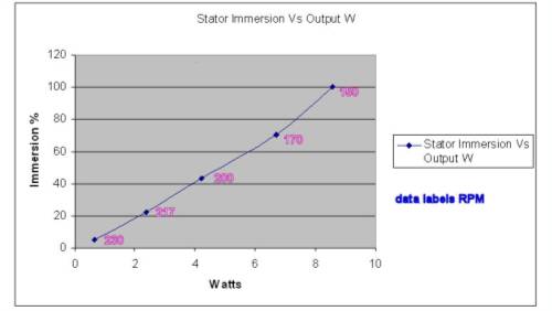
As you can see, the relationship between immersion and output power is close enough to linear and the speed increases from 150RPM at 100% coverage to 230RPM at 5% coverage
Daryl |
| |
dazz
Regular Member
Joined: 15/04/2008
Location: Posts: 78 |
| Posted: 09:02am 21 May 2008 |
Copy link to clipboard |
Print this post |
|
well this came out pretty blurry, so for those interested, the values of RPM are from Left. 230, 217,200,170 and 150
Daryl
|
| |
Gill

Senior Member

Joined: 11/11/2006
Location: AustraliaPosts: 669 |
| Posted: 10:51am 21 May 2008 |
Copy link to clipboard |
Print this post |
|
dazz,
Great Idea.
It's not the value and uses of such a device that I would question, that's a given, it's the engineering and control to achieve it that I see as the big problem.
The one feature that stops me every time with this idea has been the plastic splines of the rotor sliding in & out (up & down) on the stainless shaft. It will quickly ware and don't see an acceptable period of use for all the effort of creating it.
Also of concern is the power to drive such a device. It would need to be less than the extra gained by the faster gust response time.
However such concerns are the challenge where great strides forward are made. I think a sketch or two with pics of the prototype would be of interest to several members including myself. It may not be every bodies cup of tea but such an idea turned into a working model is without doubt an achievement to be proud of.Edited by Gill 2008-05-22
was working fine... til the smoke got out.
Cheers Gill _Cairns, FNQ |
| |
dazz
Regular Member
Joined: 15/04/2008
Location: Posts: 78 |
| Posted: 11:48am 21 May 2008 |
Copy link to clipboard |
Print this post |
|
Hi Gill,
Those two issues I also isolated as being possibly problematic. A picture might help explain the workings but a diagram might be better to show the hidden bits. I'll see what i can do about it.
The mechanism is pretty simple and as cheap as it gets.
My first thought was to use a servo for exact control but I decided a simple DC winch would do the job, probably just as well for the control needed, and at a fraction of the price.
The winch is the little 12V window winder motor you can get from Oatly for $12. It has a 10mm shaft attached and uses a nylon cord as the cable. A stainless light cable would be better but it's just a prototype
It draws 24W to lift the hub and 6W to lower it. This it can do fully in about 1/2 second. So on average you would be looking at 15W for 1 sec per gust. If your gust is not exceeding that well and truly then it's not a gust worth catching. As for control, pulsing the winch allows about 5% increments in immersion, each way. This is probably about as much as would be needed
The rest of the gear uses so much less power than the motor, it's not worth worrying about.
As for the splines. Well with full spline contact(ie the entire length of hub splines in contact with shaft splines) there shouldn't be any more wear on the hub splines moving the hub up and down as it would in normal 100% coverage position. Both the Hub and shaft are moving at the same speed.
But when say only 5% of the hub splines are in contact with the shaft splines, well the forces are much greater. I talked to a fitter and turner about it and the simple solution is to cut a piece of the spline section from a second shaft and turn both so that the new piece fits on the original shaft. You then have an extension to the original shaft spline length. After that there is always full contact of hub splines with shaft splines. And there should be no extra wear than normal.
I have been monitoring the hub splines since I started and there hasn't been any noticable wear even without the spline extension. So it may be more hardy than we fear.
My other thought regarding hub spline wear is to drill out the hub centre and insert a moulded spline section made from polyurathane. You could have a box of very cheap spline replacements handy to refit whenever needed.
Daryl
|
| |
robbo

Regular Member
Joined: 25/03/2007
Location: AustraliaPosts: 71 |
| Posted: 12:25pm 21 May 2008 |
Copy link to clipboard |
Print this post |
|
Hey Guys,
Just a quick thought. Maybe far too simple.
What happens if we insert a correctly tensioned spring between the hub and the stator (along the shaft itself).
With the tension released on the spring, the hub could sit at 5% immersion.(No wind). If cut/made to the right length.
When the blades get a gust full, the prop and hub assembly will "fall" into the stator and get a greater immersion %.
This will depend on the amount of wind pushing the blades.
No motors, or electronics, no use of all the recenlty obtained power. To simple ?
I am thinking the only thing to stop the hub sliding is the tight fit of the hub on shaft. Maybe a little filing for easy sliding and grease ?
Would the reaction time of the spring loaded hub be sufficient, or will it fall into the hub too early ?

"the Earth was not given to us, by our fathers, rather, it is lent to us by our children". |
| |
dazz
Regular Member
Joined: 15/04/2008
Location: Posts: 78 |
| Posted: 01:00pm 21 May 2008 |
Copy link to clipboard |
Print this post |
|
Hi Robbo,
There is a device around called a "Floating Hub" This has springs that do something similar to what you are talking about. It is I believe though designed for the cogging effect. I think the hub remains out, where it can start turning easily, until the wind blows, then the hub is forced onto the stator.
The problem with a simple spring system is that you are basically confined to in or out. A gust capture system would be designed to operate at optimal immersion. This may well take the form, for example, of the hub being immersed to just the right % to make the blades spin at 150RPM in the prevailing average wind speed.
If the general wind blowing is moderate, this might mean say that the hub is set at 70% immersion and then locked down full in gusts. Of course the immersion % would be worked out and set by the algorithm of the MCU.
There are all sorts of things that can be taken into account. The RPM might be set so that on average the stator is generating cut in voltage, and this in turn might take into account feedback from such things as the load and state of charge of the batteries.
Daryl |
| |
Gill
Senior Member
Joined: 11/11/2006
Location: AustraliaPosts: 669 |
| Posted: 01:17pm 21 May 2008 |
Copy link to clipboard |
Print this post |
|
robbo,
These ideas look good on paper yet when built fail to work due to the exacting nature of requirements. Very much like centrifugal bob weights adjusting prop pitch. Great in theory but in practise very difficult to tune.
We see thrust build up along the shaft to cause furling, to use this pressure to engage the hub means it is set for one value only. So it has value going from say a steady 8kph to a 15kph gust but no value going from a steady 13kph to a 20kph gust or at other settings.
Further, this method is very reactionary in that it needs the pressure to work therefor you are already in the gust. As Gordon identified with MPPT discussions some preempting of the gust is better. this is more do-able with a pre sensor of some kind and electronic control of the engaging mechanism. Dazz's 0.5 sec to fully engage shows the kinds of speed needed.
Whilst not so keen on you're idea, it is however still possible.
was working fine... til the smoke got out.
Cheers Gill _Cairns, FNQ |
| |
dazz
Regular Member
Joined: 15/04/2008
Location: Posts: 78 |
| Posted: 04:35pm 21 May 2008 |
Copy link to clipboard |
Print this post |
|
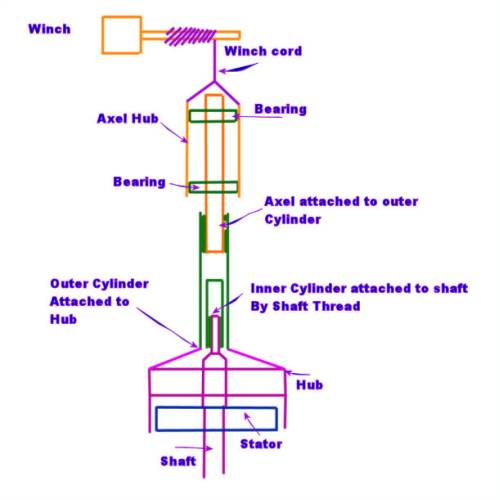
The only bit that probably needs explaining is that the inner cylinder is a snug fit with the outer cylinder. It's purpose is to keep the Hub centered as it's raised. Without the white screw down knob on the top of the hub(which I removed) the hub has a slight looseness which increases as less spline length is on the shaft, when the hub is raised. since the inner and outer cylinders spin together, there is no need for extra bearings here.
The inner cylinder could be dispensed with if the shaft splines are extended.
Note also that I have a vertical mounting with the hub above on my test unit. For a horrizontal design a light spring will be needed once the hub is raised past the strong magnetic pull of hub back over stator
Daryl |
| |
herbnz
Senior Member
Joined: 18/02/2007
Location: New ZealandPosts: 258 |
| Posted: 07:56pm 21 May 2008 |
Copy link to clipboard |
Print this post |
|
Hi Daryl
Well worth persuing, You may or may not realize that it is commonly used on hydro plants to fine tune the optimin operating point. Personally I use the rotor position as an indicator then adjust the turns accordingly. In practice all this is not practical on windmills.
I have mentioned the idea using springs as suggested above by Robbo on this forum before feedback was not positive but i see potential.
I also have similar wind to you, on coast but mountainise hills.
Herb |
| |
dazz
Regular Member
Joined: 15/04/2008
Location: Posts: 78 |
| Posted: 09:04pm 21 May 2008 |
Copy link to clipboard |
Print this post |
|
Thanks Herb, I didn't know that! I'll have to investigate :)
BTW, some of you may have realised that there aren't a couple of parts in my design that are figure skating performances. Axel/Axle I can't see the difference  Spelling isn't exactly my strong point. but for the record, the Axel was a typo...twice! Spelling isn't exactly my strong point. but for the record, the Axel was a typo...twice!  |
| |
dazz
Regular Member
Joined: 15/04/2008
Location: Posts: 78 |
| Posted: 02:08pm 22 May 2008 |
Copy link to clipboard |
Print this post |
|
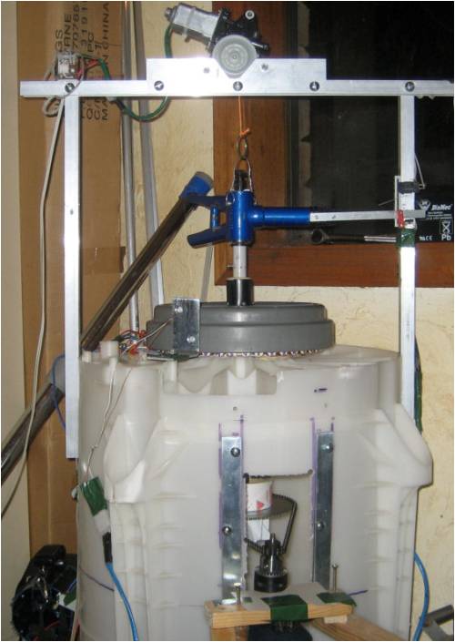
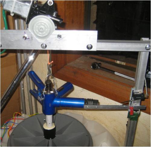
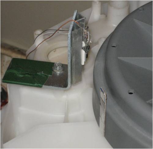
ok, here are a few pics of the set-up. Keep in mind I was trying to keep it as cheap as possible and still functional. So it's not my proudest engineering feat. And appologies for the messyness. My wife got sick of it being on the dining table  So it's in the spare room sharing space with the vaccum cleaner. So it's in the spare room sharing space with the vaccum cleaner.
The second gives a good view of the top and bottom limit micro switches and the red thing is an end on the linear pot slide which provides the position
The 3rd pic is a close up of the IR optics for RPM measurement. The silver pickup reflector can also be seen on the hub
|
| |
grub
Senior Member
Joined: 27/11/2007
Location: AustraliaPosts: 169 |
| Posted: 10:49pm 23 May 2008 |
Copy link to clipboard |
Print this post |
|
Here is an idea to consider. How about rotating weights that as they rotate faster they lift the magnetic hub up onto the stator, or the stator onto the hub, like the rotating governers used on steam motors. As the speed increases from a set minimum or preferred rpm, like 150 rpm, the about of "overlap" also increases until full depth is reached. When speed drops so does the governer and the "overlap". A bit of fine tuning with weights and lengths should have the system running at its sweet rpm whenever the wind blows. |
| |
Tinker

Guru

Joined: 07/11/2007
Location: AustraliaPosts: 1904 |
| Posted: 10:42am 24 May 2008 |
Copy link to clipboard |
Print this post |
|
I like your 'engineering' solutions Dazz, bicycle crank hub for a bearing holder - brilliant
For that SMFIS idea to work well in practice you might have to invest in an anemometer and use the feedback from that to adjust your wiper motor drive. The anemometer has a much quicker response to gusts than any part of the wind generator.
Grub's idea would work in slow changing wind speeds, me thinks it'll react too slow in fierce gusts.
Klaus
Klaus |
| |
dazz
Regular Member
Joined: 15/04/2008
Location: Posts: 78 |
| Posted: 03:39pm 24 May 2008 |
Copy link to clipboard |
Print this post |
|
Cheers Klaus
I picked that as a solution because the bearings are not only rotational but thrust bearings as well. Both the rotational and thrust aspects of both bearings get used in the lift/drop cycle. I know you have noticed this already, just elaborating on the functionality for others.
I got the whole bike minus the front wheel from the council tip shop for $1. Well it was my second bike. The first time, the pedal hub axle was bent slightly, which only showed up once it was spinning at 100RPM.
Just goes to show, sometimes bikes are sent to the tip for a reason
The idea of using an anemometer is great and makes a lot of sense since it would have a very small inertia compared to the windmill. I have a weather station hooked up to the computer, and I'm pretty sure I can extract live data from it to be used in a VB program. Thanks for the suggestion!
Daryl
|
| |
dazz
Regular Member
Joined: 15/04/2008
Location: Posts: 78 |
| Posted: 03:52pm 24 May 2008 |
Copy link to clipboard |
Print this post |
|
Just had another thought.
To get really extreme on the idea of sensing gusts, I just worked out that if there were four wind sensors 7m from the tower at points N,S,E and W then they could sense a 50km/h wind gust with enough time to drop the hub before the wind reached the windmill.
Well it would be a little over 7m to detect the same gust that came from NW, NE etc but I couldn't be bothered doing the trig.
If it was a situation like mine where winds are almost always between S and N covering W and almost never SE, E or NE then I could probably get away with 2 sensors at NW and SW
Daryl |
| |
