
|
|
Forum Index : Windmills : Single Dual Stator windmill
| Author | Message | ||||
| dazz Regular Member Joined: 15/04/2008 Location: Posts: 78 |
Hi all, I've been playing with an idea and I'd like to open it up for comment. I'm contemplating a Dual stator windmill that runs as a single stator at any one time. One stator for low winds, the other for high winds. I have had a good look at the dual stator designs that others have come up with and they do look appealing but I was just wondering about the pros and cons of a slightly different approach. This design would have the two stators mounted as normal for a two stator design. The hubs also are attached to the shaft as usual, except the top of the hubs are back to back. Instead of using rotary bearings, I was thinking of linear bearings, so that the whole shaft can move freely along it's axis. the Hubs are set on the shaft so that initially only one hub covers it's stator. If the turbine blades are pushed in 3cm, the hub slides off the first stator and the second hub slides onto the second stator. And here's the tricky bit. At the rear of the shaft on the opposite end to the blades, is a spring which keeps the shaft "forward" until the wind reaches a point of 600RPM. at this point the spring starts to compress and so Hub1 starts to disengage it's stator and Hub2 starts to engage it's stator. By 700RPM the spring is fully compressed and now Stator2 is fully covered with it's Hub and Hub1 is fully disengaged. During this period of transition, both stators are providing a proportion of the power. Ok, so why do all this. Well, firstly it makes a windmill which runs on the correct stator at the low speed range and then the correct stator for a high speed range. Secondly, if the windmill is running in the low range then the blades aren't wasting energy driving an innefficient generator which is designed for a high speed. And the same applies when it's running in the high range. All the energy of the blades is powering only a stator built for the speed range it's in. I realise that the blades also will be designed for a certain speed range, but at least it can produce a useful increase in power output when it's running outside the designed speed range of the blades. Here's a graph of what the output might look like with Stator1 setup as 24V 80SP Star and Stator2 set up as 24V 80SP Delta 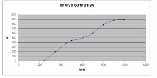
My Thanks to Michael at EcoInnovation for kindly letting me use his data to create the above graph Daryl |
||||
Hybrid Newbie Joined: 05/05/2008 Location: AustraliaPosts: 19 |
Sounds good Daryl. A file line between <on/off>. I hope it works for you. I've yet to start with windmill stator for power. I will later. Cheers ! --Anthony Petrol FWD & Electric RWD |
||||
| dazz Regular Member Joined: 15/04/2008 Location: Posts: 78 |
For those who hate working things out from descriptions, here's a diagram. Actually, when I did the drawing, I realised the hub bottoms would be facing each other, not their tops as I described earlier. 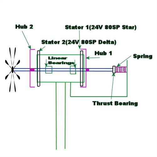
Daryl |
||||
Gill Senior Member Joined: 11/11/2006 Location: AustraliaPosts: 669 |
Dazz, I like your thinking. Very innovative. Though I see it's output as to be compared against a single rotor design rather than a twin. It's min and max is still the output of one rotor though when set up right the combined power outputs will follow the wind power rather than it's velocity curve I feel. Great! 
Would not the combined outputs of 2 individual fixed rotor wind gens, if wired the same, be more though? was working fine... til the smoke got out. Cheers Gill _Cairns, FNQ |
||||
imsmooth Senior Member Joined: 07/02/2008 Location: United StatesPosts: 214 |
I agree with Gill in that you will get more output if you just leave the two stators connected. PowerOne makes an inverter that I have an I on that allows you to select the amount of wattage you want to draw for a specific voltage or rpm. This way you can put a low load at low rpms and increase the load as the rotor spins faster. I think that when you start getting into more complicated mechanical designs the risk of failure increases. |
||||
| dazz Regular Member Joined: 15/04/2008 Location: Posts: 78 |
thanks guys 
imsmooth, I appreciate what you are saying. These sorts of things are not everyones cup of tea. But the risk of failures isn't something that bothers me in a new design. In fact I relish them and expect them. It gives me an opportunity to make the next one better.(As long as it's not the sort of failure that ends up hurting someone) Regarding getting twice the power from two fixed stators: I totally agree with you guys. It's not something I actually thought of  (is that the embarrassed icon?) (is that the embarrassed icon?)
I didn't give enough thought to the wiring selections for the two stators. The power/RPM curves overlap too much Let me get back to the purpose of this design. It's not to create as much power as possible at any given time(as would be the purpose of a fixed dual stator design) It's purpose is to produce a wider spectrum of wind strenth that gives a useful increase in power, than could be achieved with one stator. It's true, running two stators with a 80SP-24V-Star setup could provide around 1200W if they could be pushed to around 800RPM The disadvantage of course is that in light winds this setup won't reach cut-in until around 280RPM Ok, so I went back and more carefully selected my wirings for the two stators, and just for fun added a Star to Delta Switch on each stator. I came up with the following: Stator 1 is a 60S-24V system with a switch over function that allows Star or Delta Stator 2 is an 80SP-24V system also with a switch over function for Star or Delta So from 0-80RPM Stator 1 is engaged and switched to Star. Stator 2 disengaged This starts producing power above cut-in at around 25RPM rising to 35W at 80RPM At 80RPM Stator 1 is switched to Delta and stays engaged up to 300RPM, Stator 2 stays disengaged. This produces power from 40W at 80RPM to 90W at 300RPM At 300RPM Stator 1 disengages and Stator 2 engages in Star. 300RPM in the 80SP-24V setup is 100W. This is continued up to 650RPM where output is 500W At 650RPM Stator 2 is switched to Delta and produces 500W. This then goes up to over 1000RPM where this configuration peaks at around 1KW Presuming the system can hadnle this speed it would probably be a good furling point. This entire setup is just one combination of wirings, perhaps there is better, but it illustrates my point. Your getting wattage above cut-in from 25RPM all the way up, and it's always increasing as the wind increases. Assuming you are just using the raw DC voltages from two parallel stators set up for 80SP-24V then the cut-in will be around 280RPM and yes at 600RPM you will be getting twice the power of my system but I'm wondering how much like the tortise and the hare is it? My system will be collecting power steadily for the two weeks of light winds then half the power for the 2 windy days. As opposed to nothing for 2 weeks then twice the power for 2 days. Which one contributes more power in the long run? No - Seriously, which one? I don't know the answer to that
Also note that two fixed 60S's give a maximum of 200W I was thinking that by the end of this thread, if people seem to think it might be a good system, then I might try building one. I have about 7 F&P's now and one of them is a 60 so that could be handy. Also with 7 shafts around I can afford to not use the linear bearings in the first test unit and just see how it goes. If I wear a shaft out, well there's more 
Daryl |
||||
| KiwiJohn Guru Joined: 01/12/2005 Location: New ZealandPosts: 691 |
Dazz, did I miss it? I mean the obvious plus point that your scheme has the cogging of only one F@P at start up? I think your scheme has a lot of potential if you have a lot of light wind days.
I do wonder though if you would be able to get a smooth transition between the two. Wont the low speed rotor tend to 'hold on' to its position until finally lets go and the high speed rotor get to grab it's stator and pull it in? |
||||
| dazz Regular Member Joined: 15/04/2008 Location: Posts: 78 |
Hi John, Nice one! something else I hadn't thought of
The transition I'm not really sure about. you could well be right there. Annother associated issue is that the force of the wind must be able to push the first hub off it's stator. Is this force big enough? I do know from my SMFIS work that when lowering the hub onto the stator there is no force pulling it in and then suddenly a lot of force pulling in, which seems to stay roughly the same for the rest of the lowering. I'm hoping to find a point where the forces on the hubs are roughly even but opposite, but who knows. Maybe the wind force is strong enough that it doesn't matter. If there is a quick transition at the end as you suggest then perhaps a shock absorber of some kind will be needed too. Selecting the spring is going to be difficult. If I want the changeover to be at 300RPM then i'll need to measure the axial force at that speed, or at least find the relationship between the speed and that force As for light wind days, well here in Tas is a bit like NZ I guess. We are in the roaring 40's so we get our fair share of windy days. But then we also get these Highs taking up position over the SE of Aus and we can get weeks of light winds. The wind does get strong though. 70km/hr winds are quite common. A few weeks ago we had gusts at 150km/hr and I think there were reports of 180km/hr in the State. Some of the big gums that have been badly hit by the drought came down. Not good weather for windmills either I guess. Daryl |
||||
| Hybrid Newbie Joined: 05/05/2008 Location: AustraliaPosts: 19 |
Daryl by sayin, a file line between <on/off>, I was meaning from 1 stator to the other. A selector fork (like in a gearbox) could shift L/R by activating an electro magnet either side of the fork by switching. Might sound crazy, but what about a gearbox with 2 stators ? Shift gears by electro magnets & switch to delta. Cheers ! --Anthony Petrol FWD & Electric RWD |
||||
| dazz Regular Member Joined: 15/04/2008 Location: Posts: 78 |
Hi Anthony, A valid idea I feel. There are probably many ways to change from Stator1 to stator2. I was even considering using the SMFIS system at one stage. Two things to keep in mind. we want to avoid using power to get power if at all possible. An electromagnetic switch-over such as you suggest would probably require powerful electromagnets, using lots of current. How much this may eat into what the mill is actually producing may be an issue. The idea of using the spring is that on the surface it's simple and the power to effect the changeover from S1 to S2 is provided free by the wind. We also need to be mindful of what Imsmooth said. The more complicated it is, the more prone to failure. In concept, the changeover from S1 to S2 is progressive in a very limited range of wind speed. This means that it's not a case of on/off. At some point in the changeover S1 will be covered by it's hub by 50% and at the same time S2 will also be covered by it's hub by 50% The purpose of this is to provide continuous power during the changeover and more importantly to greatly reduce mechanical shock during the changeover. In the changeover the shaft goes from driving the fairly easily turned H1 to the H2 which is harder to turn. This could present, in some circumstances, a rapid change in RPM. not good. Besides which, disengaging S1 fully then engaging S2 would be mechanically a lot more complicated BTW, the changeover of S1 to S2 does not change the Star/Delta setting. This is part of the stator wiring system and is done seperately by electronics. Cheers, Daryl |
||||
| GWatPE Senior Member Joined: 01/09/2006 Location: AustraliaPosts: 2127 |
This is a 24V setup, from your description. What coil resistance will the delta configuration have? I cannot think how the stator would dissipate the 1kW that would be produced in the copper and the iron at 1000RPM and 40A. There would be significant rectifier losses as well, considering the AC frequency produced at 1000RPM. 56 magnet poles = 28 transitions per revolution. This equates to 466Hz. Std bridge rectifiers may not be up to it. What size blades do you think will be needed? What windspeed do you think this configuration might operate? Do you consider gearing may be required? Wind at 10m/s has approx 500W/m^2 of rotor blade area. Assuming the generator is 100% efficient. A blade can harness approx 1/3 of the wind energy, this gives an approx output of 166W. This would mean that if the generator was 100% efficient, then you would still need 6m^2 rotor area. Inefficiencies with the generator or gearing all increase the wind capture area required. You may try and rate for a higher windspeed. This is not however really very useful. .. .. Gordon. become more energy aware |
||||
fillm Guru Joined: 10/02/2007 Location: AustraliaPosts: 730 |
Hi Dazz I hope you have a well equipped machine shop and a lot of time and money to make such a complex configuration , the hard chrome bar to run on the linear brgs and alignment with in a purpose machined housing for those bearings is a bit more involved than drawing a few boxes on a computer and to me a bit over the top to gain 400 extra watts out of a two trashed washing machine motors from the dump . My dual which starts in 8 to 10 klm starts producing , in 11klm and tops at 600 watts @ approx 40 klm at 420 RPM with a 3.2mtr dia rotor , to double the output the cheapest way is to build a second gen .. I might be wrong and you do own a machine shop , have access to cheap linear bearings and all the other bits and you eventually build this design and it works , I hope so , as you asked in the first line of your first post on this idea , you have my comment. PhillM ...Oz Wind Engineering..Wind Turbine Kits 500W - 5000W ~ F&P Dual Kits ~ GOE222Blades- Voltage Control Parts ------- Tower kits |
||||
| dazz Regular Member Joined: 15/04/2008 Location: Posts: 78 |
Hi Gordon, Well my 80SP Star setup seems to have 0.8ohm per phase so in Delta I think it would be 0.4ohm per phase. I know! the mind boggles. all I can say is I got the test data from the EcoInnovation power graphs, so I'm assuming it works. They actually say that something over 1000RPM is above the reccomended running maximum speed for the Smart drive units. Having said that, some of their tests go close to 1500RPM I did read somewhere that more specialised rectification is needed at the higher frequency output that these thigs can do. Can't remember where. Thats a very good question, hopefully some of the forum members with actual windmill making experience will have some suggestions. I think maybe a typical blade setup for 80SP-24V Star might be something to aim at. Only guessing here but perhaps 1.5m blades X 3 Whether this will run at 800-1000RPM in winds between 80-100km/hr I don't know, but the type of blades will be important at these speeds. ie PVC blades may be too weak for these stresses. I wouldn't think that I would endevour to use any type of gearing. I get the feeling that doing so would severely restrict the windmill from producing at low wind speeds with blades that are designed more with higher speeds in mind than greater torque. I have seen a few descriptions now of 3 bladed turbines that they say run to 600RPM as an upper limit. What wasn't pointed out in these descriptions is whether that upper limit is due to blade design or because the windmill is fully furled at that point. Yeh, certainly tricky! but just going on these figures it's interesting to note that if the windmill has 1.5m blades(which doesn't seem excessive compared to many of the designs on this site) would give a blade area of 7m^2. This would mean perhaps 195W at 10m/s Looking beyond that, a strong wind of 80km/hr is 22m/s or 8.8 times the power(cube relationship) or 1.7kw This would leave a bit of room for losses I would imagine. But in the end, I don't much care if the windmill can produce 1kw in 100km/hr winds. The main thing I was aiming at was useful power in slight winds and for the power curve not to be leveling off at the top end. The top end being somewhere over 70km/hr I think. The idea of the 80SP 24V Delta might in the end be scrapped but considering how often we get winds above 70km/hr here, it just seems a shame to be topping out in power at around 50-60km/hr Daryl |
||||
| dazz Regular Member Joined: 15/04/2008 Location: Posts: 78 |
Thanks Phill, I do indeed value your comment. It's a pity that with 600+ registered users there isn't more input to project threads. So for those few who have been bothered to spend time passing on their thoughts, I'm very thankful. Oh, and I do have a great machine shop! And a great electronics lab and computer lab and a couple of general workshops. Linear bearings aren't cheap, I agree. But I'll see how i go. There are other ways to do the same thing. Daryl |
||||
| Jarbar Senior Member Joined: 03/02/2008 Location: AustraliaPosts: 225 |
Hello Daryl and Phill,I read daily all the posts and admire greatly what you both have and intend to do.What you both also have is your health.Man recently landed a device on Mars and although a potential large waste of money and time,who knows what benefits it may bring.The fact that we can toss around ideas no matter how absurd or creative they may be only limited by our own knowledge and resources.But in this forum comes seeds of inspiration. Phill,your Mill and photos really showed me what is possible with outputs visible.Not just a set of theoretical figures. Daryl,your drawings and concepts have me thinking.Go for it. Going to Mars took some radical thinking,and not every attempt was a winner.Balloons and air bags how could that be viable.But it worked. Keep up the great posts and when I get my health back watch out. Regards Anthony. "Creativity is detirmined by the way you hold your tounge".My Father "Your generation will have to correct the problems made by mine".My Grandfather. |
||||
| dazz Regular Member Joined: 15/04/2008 Location: Posts: 78 |
Thanks Anthony, I hope you are well soon! Gordon, I looked at the wrong numbers on my note pad. The resistance of one phase in Star is 0.4ohm and I reconnected into Delta and measured and it was 0.1ohm Obviously with such low values allowance must be made for considerable error Daryl |
||||
| GWatPE Senior Member Joined: 01/09/2006 Location: AustraliaPosts: 2127 |
Hi dazz, the computer lab must be providing wrong numbers as well. Increasing the wind velocity from 10m/s to 22m/s increases the power by a factor of 10.5, not 8.8. Gordon. become more energy aware |
||||
| dazz Regular Member Joined: 15/04/2008 Location: Posts: 78 |
Hmmpff Perfectionist! 
|
||||
grolly Regular Member Joined: 19/05/2007 Location: AustraliaPosts: 62 |
dazz, How about a set of weighted balls to move the second hub over the stator, so you have a 2 stator unit at the mean wind range, and another set of balls to pull the first hub off the stator at high wind speeds. Also thought that moveing the hubs would be easier and cheaper, so you could secure the prop and shaft, owing to the high latteral forces that you would have when it furls at 1000 rpm ( mine keeps chewing out the rear bearing housing) grolly I have bought the farm...now I AM powering it... |
||||
| dazz Regular Member Joined: 15/04/2008 Location: Posts: 78 |
Hi grolly, I imagine the balls system would have trouble coping with yaw, especially during furling Daryl |
||||
| The Back Shed's forum code is written, and hosted, in Australia. | © JAQ Software 2026 |
