
|
|
Forum Index : Windmills : Working on a 10 hp motorconversion
| Page 1 of 5 |
|||||
| Author | Message | ||||
| Dinges Senior Member Joined: 04/01/2008 Location: AlbaniaPosts: 510 |
After the first small motor conversions (none are yet flying) I decided to tackle a larger project. About a year ago I finally acquired an old 10 hp motor to be converted to a permanent magnet (PM) generator. Work has been progressing slowly but steadily. Initially I intended to just make a new PM rotor for it but later decided to do a full conversion: a new rotor and a rewind. This is so far the largest motorconversion I undertook. It will likely be the final one too. Larger conversions are frought with too many problems. A 5 or 7.5 hp motor is the nicest size, I think. 10 hp is just a tad too large (for me). And to think that Zubbly was considering doing a 25 hp conversion... (me shudders). This is also my first conversion where I use the 'JacquesM' method of decogging, as opposed to the usual helix-method. Hopefully the theory and calculations were correct, otherwise I'll end up with a 20 kg magnetic paperweight. The progress so far: the coils in the stator have been removed (sept. 2007). A new rotor has been turned and milled (finished in march 2008). At the moment I'm glueing the magnets on. 36 pieces of N42 2"x1"x.5". A scary job. Sometimes things look nice on paper (or the CAD screen), till you finally hold the workpiece in your hand in real life and see and feel how large and heavy it really is. The photos don't do justice to it. 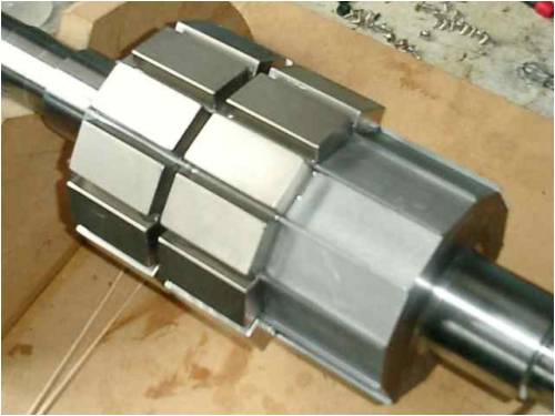
Anyway, I'll try to describe the progress on it in this thread. Plenty more photos, along with short comments, can be found here: http://picasaweb.google.com/motorconversion/75KWMotorConvers ionBlueMonster Hope others will enjoy it too, even though this board is mostly focused on using F&Ps. Peter. |
||||
oztules Guru Joined: 26/07/2007 Location: AustraliaPosts: 1686 |
Looks the goods Peter, serious size too. I have a few of these things now (10hp), but can't bring myself to do a conversion with them. Think I will do an induction grid tie instead. These bigger ones I have begun playing with lately have swung me toward grid tie. They will have to be single phase, I don't have 3 ph here. Am interested in your diagrams of the Jam methodology for this rotor. Are there clearer pictures else where, or is it this browser. They are washed out, other pics are fine on your site. I have built a decent axial but not flown it as have no batteries here. But it is good to test three phase rewinds (use as a driver). I still reckon that whilst they have brilliant performance, they are still not robust enough to use long term. Motor conversions and induction units are well engineered. Most interesting. Now Zubbly is no longer with us, you seem to be holding the flag up. Well done. I was thinking of him last night as I used up some more of his transformer paper he sent me for another motor rewind. .........oztules Village idiot...or... just another hack out of his depth |
||||
| Dinges Senior Member Joined: 04/01/2008 Location: AlbaniaPosts: 510 |
Thanks Oztules. Not sure what browser you use, but to see the full-size images, you can click either on the magnifying glass or on 'view largest photo'. Alternatively, you can go to my old gallery (http://www.anotherpower.com/gallery/album68?page=5) If that still isn't clear enough let me know and I'll either send you the CAD files (.dwg or .dxf format) or zoom in on the parts you're interested in. Anyway, it's just a plain 'Jam' conversion, as explained in the decogging tutorial. It worked for JacquesM so I expect it to work for me too, but it's still a bit exciting as there's a lot of time and effort (and money) invested in this conversion which uses a method I've never used before. As far as induction grid tied goes, it may perhaps be an idea to still rewind the motor to, say, an 8 or 12 pole (if it's originally a 2 or 4 pole). The rotor wouldn't have to be changed, but rewinding to more poles would mean that it'd start generating at a more usable RPM without the need for gearing (or at least, could use a much lower gearing ratio). Hm. And you're *again* rewinding a motor ? Might as well start up a business... |
||||
| oztules Guru Joined: 26/07/2007 Location: AustraliaPosts: 1686 |
Thanks Peter, the anotherpower site was perfect. The Jam version looks right, but it is different. I trust you will have it cog free. I expect perfection from you (rather than rough and ready tules). However, I don't think delta would work as well as star with this one. The non-geometrical aspect may cause circulating currents in Delta. Jerryrig would be ok though. The larger ones over here are 4 and 6 pole units. I have wound a consequent pole 12 pole, but it did not self generate with caps. I didn't hook it to the grid, (except as a motor) but I recall Flux saying reactance limits come into effect for high pole counts. So 8 may be the economic limit. On a larger diam motor, it may be ok. 8 pole should only be 5 or 6:1 which must be easier to turn than 10 or 20:1. We'll see what gearbox I can scrounge up. ......oztules Village idiot...or... just another hack out of his depth |
||||
SparWeb Senior Member Joined: 17/04/2008 Location: CanadaPosts: 196 |
Peter, This looks fantastic. I really like some of the new ideas, like the fences on the rotor to keep the magnets from drifting around as you locate them. As I browsed through your pictures, a few things came to mind. Does your hub plate have to be stainless? You can use mild steel: easier to weld, and you could conceivably build it with stock components, ie., sprocket and hub assembly. If you make blades that turn clockwise, a bolt in the end of the shaft will help keep the hub on (I made blades before making the shaft, then realized that I had missed an opportunity by making blades that turned counter-clockwise). Just an extra safety feature. There's a key on the back end of the shaft in your drawings. Are you going to put something there? Encoder? Brake? Early pictures show a lot of effort to test the windings. Then you removed them. Did you intend to keep the stock windings at first? Did a specific test result make you decide to re-wind? I'll be watching this space... I'm not working on my next motor conversion, these days, so I'll live vicariously through you. I'm doing other things this summer that fall into the category of "system fortification", ie, replacing the cheap inverter with a real one, changing all connections and equipment to 24Volts, fusing and installing circuit breakers, etc... Steven T. Fahey |
||||
| Dinges Senior Member Joined: 04/01/2008 Location: AlbaniaPosts: 510 |
Thanks Steven. I particularly like the little ridges too. In fact, if it weren't for them, wrestling the magnets in place as they sliver around on a coating of epoxy would be practically impossible. The downside is it takes a fair amount of machining (milling). The hub plate doesn't *have* to be stainless. But, I like stainless steel for its corrosion resistance. No painting and maintenance required. I'm lazy: I don't mind building it once, but I dislike maintenance and repair. Also, austenitic stainless steels (AISI 304, 316) are a joy to weld. I'll keep the clockwise turning blades in mind, but it already was my intent to not only let it turn that way but also to lock all nuts and bolts by a mechanical means (either locking wire or locking plates). Especially the central bolt that connects the hub to the shaft. IMO, windturbines require aviation practices, standards and quality levels in building and maintenance. Yes, the key on the back is there so I can install a disc brake on it, as Bruce has done with his F&P. I like the idea of 'belts and braces' safety. Furling plus a way of mechanically positively stopping the blade. This would also be handy during raising and lowering of the tower. I'm also keeping in mind Oztules' method (rather: Southern Cross method) of furling/stopping the windturbine, but at the moment I'm partial to a braking mechanism. I still intend to mount a temperature sensor in the stator (don't know how yet, haven't considered these issues much so far) and I'd like to have a way to tell RPMs. Maybe an optical through-beam photoswitch and vane inside the motorhousing ? Don't know yet. But it would be handy in the case of star/delta switching. My 3hp conversion doesn't seem to have much problem running in delta (unlike the 130 W conversion, which shows quite a bit of torque ripple when wired to delta (and without an electrical load). I figure delta should be possible, despite the risk of circulating currents, which I think can be removed by carefully rewinding (identical number of turns in all phases). You're right about the original plan to keep the stockwindings. It was originally a 4 pole and I intended to just build a new rotor with the Jam method. Then afterwards do another motor conversion with rotor and rewind. Zubbly's disease made me decide to do a rewind immediately on this motor. Unfortunately he passed away before work really started. I'd have loved to show it off to him and hear his criticisms. Another reason to do a rewind was by the negative comments about the limited usefulness of 4 pole conversions, multi-pole being much more suited for wind. So there were several reasons to do a full conversion (with rewind) on this conversion, rather than wait for the next conversion to do it on. Nothing to do with any test results, the motor windings were fine. Not only my results confirmed that but also the measurements by the motor rewinding company (who gave me the motor), which tested the stator using their high-voltage 12kV pulse tester and declared it 'good'. Looking forward to updates on your conversion too. So far, I understand your 3 hp is still flying and going strong (I assume that no news is good news :) ). A testimony to the reliability of those conversions. |
||||
vawtman Senior Member Joined: 14/09/2006 Location: United StatesPosts: 146 |
Hi Peter I've been around awhile has you know and can't remember a posting about the output from Jams decoggin design in a flying wind turbine. Maybe before my time. Nice work on your end. Thanks Mark |
||||
Bryan1 Guru Joined: 22/02/2006 Location: AustraliaPosts: 2102 |
Allo Peter, Mate wih this post you KNOW I'm getting ready to start on my 10Kw motor conversion  . Now it was awhile ago we were talking about it so get back into irc and lets gabble for awhile. I've pencilled out slab of 7" steel at work to make a new stator but I do need your advise on the mags and other considerations. . Now it was awhile ago we were talking about it so get back into irc and lets gabble for awhile. I've pencilled out slab of 7" steel at work to make a new stator but I do need your advise on the mags and other considerations.
Cheers Bryan  |
||||
| Dinges Senior Member Joined: 04/01/2008 Location: AlbaniaPosts: 510 |
Vawtman, I don't know whether that conversion of Jam (I think it was a 5 or 7.5 hp unit; not sure) ever flew. One problem I've seen with it was that it was rewound incorrectly as only half of a 6 phase machine, not 3 phase. I do know from reliable sources (if one can consider RonB to be reliable) that it didn't cog though. Bryan, darn, just when I thought I was working on the most powerful conversion yet, you come along and start working on yet a larger one. Will this rat race never end ?! 
I'm regularly in Ross's IRC, feel free to hop in. We seem to be missing eachother lately, must be that timezone thing. I'll gladly help if I can, though it might be wiser to ask your questions in this forum, not IRC, as there a few other people (Sparweb, Oztules, Ron e.a.) who also know quite a bit about the subject. Besides, it'd help the dissemination of information/knowledge that way. |
||||
philb Regular Member Joined: 05/07/2008 Location: United StatesPosts: 96 |
Hi Peter, Your projects never cease to amaze me. Thank you for your post. It was very informative! Between Zubbly, Steven and you, I'm convinced to try a motor conversion. If you look at the link, http://www.fieldlines.com/story/2007/6/2/17930/85949, it seems I have been headed that way for some time now. The silicon steel core contributes heavily to the power output and does not create as much heat as ironless stators do. I have collected two 5 hp motors, one 10 hp and one 20 hp electric motors. All are US government surplus 460V 3 phase. I'm going to build just one more axial turbine (number 8) before embarking on a motor conversion. It will be in the same style as the one in the link, only larger. I'm looking forward to your test results. philb |
||||
| SparWeb Senior Member Joined: 17/04/2008 Location: CanadaPosts: 196 |
Peter, Thanks for the extra info. My motor conversion is still running fine. Making gradual improvements, too, as I try different connections inside it. At 12V in parallel-star, I'm getting 300W peaks. The tail furls in 30kph wind and the 8-ft prop is turning up to about 600 RPM. Currently, it's shut down as I convert everything to 24V. By the numbers, the blades are running fast (TSR too high) because they aren't loaded enough by the motor. So I'm getting Cp only around 20% or so. I put a temp sensor on my mill last fall. Since then I have witnessed no effect at all. Zero. The sensor tested ok on the ground, by putting a heating element against it. Starts reading at around 120C. Even when it was connected in Delta, and subjected to repeated shorting, accelerating, and shorting again, I was unable to provoke a measurable temperature rise. I will not bother to do this again, and I can use the wires in the tower for something else, like a proper RPM sender (gee now that's something that gives me a headache). I also want to encourage the little "arms" race - make that "armatures" race - going on. I have a 5HP and a 25HP just waiting to become my third and fourth MoCo's. And you only win when you get it in the air! Oh, and about the stainless, I hear you. Sometimes is just has to be shiny. 
Steven T. Fahey |
||||
| vawtman Senior Member Joined: 14/09/2006 Location: United StatesPosts: 146 |
Hi Peter I can't see how you could possibly decog it without skewing the stator lams. If it can be done i would stick the rotor in before you attempt to rewind it. The mags treat the coils as if they were air and so no creative winding will help you. My opinion. Mark |
||||
| Dinges Senior Member Joined: 04/01/2008 Location: AlbaniaPosts: 510 |
Oh ye of little faith...
http://www.anotherpower.com/gallery/album68/blue_monster_dra wing_3?full=1 Notice that the magnets are not at 30 deg (360 deg/12poles) but at 29.166 deg w.r.t. eachother. This method was described in the decogging tutorial (p. 14-19, 'offset method'): http://www.otherpower.com/images/scimages/3538/decogging_tut orial_V1.pdf It has been proven in the past to work. See this work by JacquesM (who seems to have copied it from Victor, who seems to have found it in commercial generators): http://www.fieldlines.com/story/2005/1/8/2291/67790 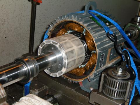
Look especially close at the spacing of the magnets on the rotor, you'll notice that in one place (~5 o'clock in this photo) the distance is not equal to the other 11 places). Stator skewing shouldn't be needed here. Yes, good point. No use spending a lot of effort rewinding only to find out later it cogs beyond belief. The rotor will have to be inserted anyway for a testrun of the test winding (single-turn wave winding) to find out the RPM/volt relationship and to determine how many turns per coil will be needed for a given cut-in voltage at a given RPM. |
||||
| vawtman Senior Member Joined: 14/09/2006 Location: United StatesPosts: 146 |
Yep.For wind she needs to be has smooth has silk.Been there.Has a motor driven gen.Who cares if it cogs. Have fun Peter and not sure why you quit IRc. |
||||
CraziestOzzy Senior Member Joined: 11/07/2008 Location: AustraliaPosts: 152 |
Great project...seems you have nearly finished yours and I have just started mine
I can really appreciate the weight of your new stator and even the complete weight of your assembled unit!!! I am considering a different approach with respect to the emplacement of your magnets and their attachment by using "glue". I am looking at using soft iron laminations to encase the magnets and help increase and direct the magnetism towards the stator. I also am going to look into the idea of a thinner shaft that is suited to the actual torque experienced-expected in the generator and the desired RPM. Also I am going to even research the idea of using a material that is lighter and stronger than a typical Fe alloy shaft...of course cost will be a determining factor! I am most impressed with your baby  http://cr4.globalspec.com/member?u=25757 http://www.instructables.com/member/OzzyRoo/ |
||||
herbnz Senior Member Joined: 18/02/2007 Location: New ZealandPosts: 258 |
Hi Peter Many thanks for sharing this info and raising another possibility. Question do you wind the stator with any allowance for the small shift in the poles ? In my mind normally the pair of magnets that are magneticlly opposite induce emf's that add together here I see a phase shift they will still add but vectorial, properly its a minor effect and would not be a power loss just voltage. Herb |
||||
| Dinges Senior Member Joined: 04/01/2008 Location: AlbaniaPosts: 510 |
Yes, that is correct, there will be some phase difference between the the various coils within one phase. This will probably mean a (small) loss in voltage and thus power too (at a given RPM). It's the price one must pay to compensate for the cogging, I suppose. I expect the phase difference not to be really a problem, but it will be an interesting experiment to watch the waveshape of the AC, both for one coil and an entire phase, and to check the phase relationship of the AC between 2 coils. I cannot compensate for it by changing the winding scheme. It's just one of those things. A compromise between no cogging and maximum output (more correctly: maximum effective use of magnets) |
||||
| Dinges Senior Member Joined: 04/01/2008 Location: AlbaniaPosts: 510 |

All magnets have been installed. Next step is to add some glass cloth around the magnets and cast the rotor in epoxy. |
||||
| Dinges Senior Member Joined: 04/01/2008 Location: AlbaniaPosts: 510 |
I've been thinking about a method to deduce RPM of the rotor for star/delta switching purposes. Might be an idea to install an extra coil of just one single turn in the stator. As the rotor turns it will induce an AC voltage in that pickup coil, the frequency of the AC being an indicator of the RPM of the rotor. Seems the simplest method to me, without a need for optical encoders, light bridges or other electrickery. I don't recall anyone else using this method. It should also work in axial flux generators (or F&Ps )
The question is how much voltage would be induced in one single-turn coil, but if it's too little the pickup coil could have a few more turns. The wire could be much thinner than the copper wire of the actual (power generating) coils. A pair of anti-parallel diodes would turn the sinusoid AC in something approaching a square wave, ready for further processing by electronics. Feel free to criticize. |
||||
| CraziestOzzy Senior Member Joined: 11/07/2008 Location: AustraliaPosts: 152 |
I agree with your idea...if the voltage is too low, you could simply amplify the signal...with some toroidal filters (remove unwanted frequencies etc) to fix any noise that may occur, if any. You would obviously need a small IC counter that are very easy to setup DIY style and require very few passive components when mounted to LCD display. I think you may have to divide the number of pulses received by half the total number of magnets (11 in your case) assuming you would be counting the peaks of each pulse. Or the other way would be to use the 6 poles of same polarity (ignoring the other 5) and use that as a measurement, which may mean you would be counting either the "troughs" or "peaks" of the square wave....just my thoughts and your idea is most interesting. http://cr4.globalspec.com/member?u=25757 http://www.instructables.com/member/OzzyRoo/ |
||||
| Page 1 of 5 |
|||||
| The Back Shed's forum code is written, and hosted, in Australia. | © JAQ Software 2026 |
