
|
|
Forum Index : Windmills : New guy experimenting with wind power
| Author | Message | ||||
Dodgeman Newbie Joined: 19/07/2008 Location: United StatesPosts: 33 |
Hello all, A few weeks ago I got my new (slightly used) Marathon Electric, Permanent Magnet, Direct Current, motor from ebay, its rated at 3/4 hp, 1750 RPM, 90 volt DC, 7.6 amps as a motor, It is just like this one http://www.marathonelectric.com/MMPS/dcdetails.jsp?item=56E1 7F1007 Somewhere I read that there is a "quarter rule" 1/4th of motor ratings? for using a dc motor as a wind generator, with direct drive, I forget where I read that but would like to get confirmation or denial on it, of anyone knows? If that is indeed the case when using a DC motor as a direct drive wind generator, I should get about 22.5 open volts DC (no charging load) at about 437.5 RPM, which will probably only happen during high winds (which are fairly abundant around here most of the year) I hope someone can confirm or deny that calculation ;) (I think) I can realisticly expect to get at least 300 RPM with a 4 ft direct drive blade (I know I could get much more with a gear or belt driven, but I think I will be going direct drive first, just to see what happens. I have built a few smaller scale DC motor wind generators just for fun, but this will be the largest motor I have used to date, the others were quite small compared to this one, none of them would generate 12 volts and none had a blade longer than 2 1/2 feet, I was only able to light a few LED bulbs and charge a 4 volt battery which was scavenged from an emergency light, for this one I have made PVC blades again, which turned out to be 4ft 4 inches long, and I built a hub out of scrap junk I had handy. See pics below if I posted correctly. Just for fun,, and just to see what happens, right after opening the motor box, I hooked up the first handy dc load I could find, a small 12vdc computer fan rated at .16 amps , I know its a small load but,,, with a turn of the marathon motor shaft,, by hand,, the little computer fan took off and ran for several seconds, I was also able to light an 1157 brake light bulb with ease, I attached a pulley to the shaft for a better grip and was able to light the bulb and turn the fan motor at the same time, Also I hooked a meter to it and read 24.2 volts dc (max voltage) when turning by hand with no load. My "quarter rule" calculation may be wayy off for this motor ;) Also, it gets much harder to turn the motor with the leads shorted together, which brings up another question I have for a braking system,,, If I wire a switch to short the leads, will this burn out the windings if it were to get spun while shorted? or will this cause it to "brake" during excessive winds without hurting the motor? I live in town so the tower height is limited to about 20 feet, I have a tree in the yard as well, so wind will be variable, but is fairly steady in this part of Southern New Mexico for a good portion of the year. I will probably be using 2 inch black pipe as that is what I have on hand, (I have used it on my smaller mills) I dont know if it will support this machine which weighs about 65 lbs. My others all weighed less than 20 lbs. I have cable for guy wires avaliable of needed but have not used guys on the tower for the smaller rigs. (Im sure it will be needed) the pipe is attached to a 3ft x 3ft x 1/4 inch steel plate as a base. I was wondering if I am on the right track with this motor/mill, I have no idea how much electricity it will create, I would like to know expected wattage (and how to calculate that from the motor specs) and about how many 12 volt deep cycle batteries should I expect to be able to charge effectivly. and anything else you all think I should know ;) I also have 1- 125 watt BP solar panel, which I would like to integrate into my power system somehow, I scored a small 16 amp charge controller from Ebay for the solar panel, and currently have it charging one older 12 volt deep cycle marine battery which I got as a "Blem" (blemished during construction) a few years ago. It seems to have trouble keeping up with charging the battery. I have some elecrical understanding but very little electronics know how. Right now, I am doing this for fun as my home is wired to the grid, I would like to power a shed at first with possible expansion in the future. I will be running ocassional power tools and lighting if possible for now. I may also use it for emergency backup power, should the grid go down, if thats possible with what I have. I have a few small power inverters one is 600 watt, with an 800 watt peak, and 3- 400 watt vector inverters, I am not sure what all I can run off of them or if they will be of much use for my needs. Here is a pic of it, please dont mind the mess, cleaning day is not until next year ;) 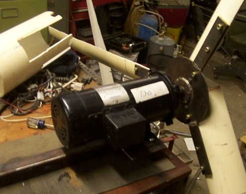
Here is a close up of the back side of the homemade hub assembley I whipped up, I hope it does not snap the shaft off the motor. 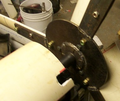
this picture below is of my first mill flying, it was a john deere generator and it made all of about 6 volts dc in a stong wind but flew very well with little noise and seemed to be balanced ok. 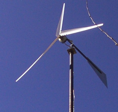
Anyway, thats where I am in my experiments, I am sorry for jumping around and for the long post, as I have so many questions, and am doing this in the least costly way I can. I hope someone can help steer me in the right direction. by the way, I have lurked around a bit for the last few weeks and I would like to say -What a great site you guys have here- very interesting stuff going on here. I hope to hang around a while and learn all I can about generating free power :) Thanks for all input Dodgeman |
||||
| Gizmo Admin Group Joined: 05/06/2004 Location: AustraliaPosts: 5182 |
Hi Dedgeman, welcome to the site. Yes you can damage the coils, if the wind is strong enough to overcome the load. Motors like the F&P have exposed windings that can dissipate the heat generated from a dead short and run away turbine, but enclosed motors like yours will cook themselves in extreme situations. I would look into some sort of furling instead of electrical braking. I see in you last photo you used one of those 24v scoota motors. I've tried that, and ended up with the same results as you. Those motors need to be geared up to work. If the shaft extended out both ends you could connect 3 or 4 on the same axis, and then wire them in series to get the higher volts. Glenn The best time to plant a tree was twenty years ago, the second best time is right now. JAQ |
||||
| Dodgeman Newbie Joined: 19/07/2008 Location: United StatesPosts: 33 |
Howdy Gizmo Thanks for the reply and nice to meet you, I was thinking winding damage could occur if high winds turned the mill when shorted, the motor gets harder to turn by hand when shorted, but, a good breeze will still turn it. I have not used a furling on my little toy mills as yet, just rigid frame so far, I was wondering how I may do that on this unit but have yet to work a furling mechanism out. I have seen pictures of the F&P motors and they look great , however, I have never seen one available here in the southwest USA, so that may be out of my reach for now. My little mill in the last photo was a generator from a John Deere garden tractor, or so I was told, it does resemble the scooter motors I have seen on Ebay, but seems a bit tougher as far as shaft size and bearings are concerned, voltage output on the other hand leaves much to be desired, its average output was about 3-4 volts with peaks up to 6 vdc in high wind, which is hardly useful to me. I mainly built it so I could -see if I can- and see how the PVC blades work, surprisingly, it has flown non stop for over a year now, but its mostly for looks and to get my neighbors used to the idea of a windmill flying in my yard  the one I am building now will be at least 2 times larger than the small one. the one I am building now will be at least 2 times larger than the small one.
I was thinking to go without furling (or braking) but that may be a bad idea for the size and weight of this contraption. My thinking behind that idea is - If the mill is facing into the wind, it will never reach 1750 RPM, so as long as I can keep it facing into the wind it will be generating, and the stronger the wind the better. I may be way off in that line of thinking as well. For now, its all just experi-mental electricity, so failures are expected so long as I can keep bodily harm to a minimum  
Dodgeman |
||||
oztules Guru Joined: 26/07/2007 Location: AustraliaPosts: 1686 |
Hi Dodgeman, Try this site to get a feel for the rpm-wind-diameter associations. http://www.alton-moore.net/wind_calculations.html For a reasonable tsr with 4' blades you should get your 1750rpm at around 38mph. At least that's the theory. Your little prop may struggle to start this . The prop unloaded will reach your 3-400 rpm at only 6-7mph winds.... but there is only 6 watts available to turn the shaft at this wind velocity..... and thats with the blades running properly. The start torque is virtually 0kg/meters.... not until 20 mph does the torque get to 40grammes/meter.. So start up may be later.,depending on the cogging effects. Anyway, try the calculator to see what power you have to work with at what revs. .........oztules Village idiot...or... just another hack out of his depth |
||||
| Dodgeman Newbie Joined: 19/07/2008 Location: United StatesPosts: 33 |
Hello Oztules and thanks for the info, I do appreciate all input but that site (and the math involved) may be a bit beyond my little dc motor mill making abilities. I may be wayy of in my (limited) thinking but I dont think I will ever acheive 1750 RPM with the direct drive to the blades I made. (possibly with gearing but I am not doing that method this go around) I do not understand -tip speed ratio- either, can the tips be spinning faster than the center? can someone explain that to me reallly slow ?
So far no progress has been made on my large mill, except for the bearing assembley, I have obtained a "neck bearing" which was cut from an old motorcycle and will be welded into the top of the pipe/tower. So much to do, so little time. |
||||
| Robb Senior Member Joined: 01/08/2007 Location: AustraliaPosts: 221 |
[quote=Dodgeman]can the tips be spinning faster than the center? can someone explain that to me reallly slow ?[/quote] If we get a kids merry go round and turn it at one revolution per day that sounds pretty dull and boring right. Your grand mother could out walk that with her zimmer frame.
Now if we enlarge the merry go round to the diameter of the earth you need a jet plane to keep up. Does that help |
||||
| Dodgeman Newbie Joined: 19/07/2008 Location: United StatesPosts: 33 |
Yes it does,, thanks,, Thats the kinda "slow" I need sometimes, which makes it easier for me to understand this stuff,
However, I may be a bit confused still. If the center of the merry go round and the outer edge of the merry go round, are marked at a given spot (say top dead center or 0 degrees on a degree wheel) and it completes one revolution, being solidly attached from center to outer, the center shaft and the outer edge will both only complete 1 revolution, therefore it will not turn the center any faster or slower than the outer?Right? It would seem that, larger diameter will only create more torque to turn the center? I looked at the calculator in the Alton Moore link, and I guess I dont understand what figures to input into it. What I mean to ask is, My PVC blades are about 4ft 6 inches long, each, this would be the radius or half of total diameter. So my total sweapt area should be 9.2ft. I guess I need to know - how does one figure out tip speed ratio to generator shaft speed ratio? I understand that: following the circumference (outer edge) of the circle, it is a longer distance around the outer edge of the blades than it would be to follow the smaller circle or circumference of the rotor assembley of the motor, (where the power generation is taking place) so if they both (blade and shaft) make 1 revolution, I dont understand how this will effect final RPM expected from a given set of blades which are direct drive? Does that make sense? or am I confusing myself with unnessessary figures? Please bear with me, I am new to wind power generation, I would like to understand what I am doing and know if I am doing it right. I have attached a quick sketch to help illustrate what I am asking, 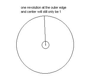
Thanks again 
Dodgeman |
||||
| WooferHound Newbie Joined: 05/06/2007 Location: United StatesPosts: 3 |
We are not talking about RPM here. we are talking about the fact that the tips of the blades are covering much more distance per revolution than the center of the blades. So the Tip Speed has a Ratio (or difference) to the actual wind speed. W o o f -={( The wind in Alabama doesn't Blow , it Sucks . . . |
||||
| oztules Guru Joined: 26/07/2007 Location: AustraliaPosts: 1686 |
Dodgeman, Yes all parts of the blade move at the same RPM, but different diameters cover different distances in the same time. At a diameter of 1m on your approx 3m blades for each turn, that point must travel 3.1417 x 1 meters to complete a turn or circle. At the 2m diam point on the blade, it must travel 3.1417 x 2 meters to complete a circle. At the tip it must move 3.1417 x 3m to complete a circle...otherwise the blade would separate and the world would cease to function as we know it. So different radial lengths of the blade move at different speeds but at the same rpm. The center has no speed at all. It covers no distance in the time that it is rotating, while the tip moves nearly 10m. Also you have confused swept area with diameter. Your swept area is (4.5x4.5)x 3.1417= 63.6 square feet Your diameter is 9' (4'6" + 4'6"=9'... not 9.2') Now TSR: Your tip speed ratio is simply the speed of the tips of the blade divided by the wind speed. eg If your tips of your blades are traveling at 100 meters per second, and the wind is blowing at 20 meters per second, the tip speed ratio (TSR) is 100/20 = 5 so you would say your blade has a TSR of 5 From this characteristic we can get an idea the performance of a blade set in a wind that you expect. As a general rule, the less pitch you carve into your blade, the higher the TSR will be. Common values are 5-7. So if we carve a TSR 5 blade of 3m (about your size) then we can say in a 10 meters per second wind that the tips will be traveling at 50 meters per second. (wind speed x TSR) From that we can work out how many RPM the shaft will be doing at 10m/s windspeed.... like this If blade = 3M diameter then it is 3.1417 x 3 = 9.5 meters around the circumference. If we turn it once, the tips travel 9.5 meters we'll call it 10meters to make this simpler. So we know that we cover approx 10m per revolution. The wind is blowing at 10 meters/second, and we have a tsr of 5 Putting it together: The tips are traveling at (10m/sec x 5 TSR) = 50 m/sec We know that they cover approx 10 metres per revolution so they must be turning at 50m/s divided by 10 meters per revolution = 5 revolutions per second. Multiply the rev per sec x 60 to get rev per min .. 5x60= 300 rpm (60 seconds in a minute) So now we know that the TSR5 blades in a 10m/s wind with a diameter of 3m will run at 300 rpm Now if you go to Alton's calculator, you can put these figures in prop 3m tsr 5 and look at the windspeed at 10m/s it should be pretty close (remember we approximated the 10m circumference) Does that clear it up a bit? .............oztules Village idiot...or... just another hack out of his depth |
||||
| Dodgeman Newbie Joined: 19/07/2008 Location: United StatesPosts: 33 |
Yes, thank you very much, that was what I was having trouble comprehending, like I said, I never have been a math wiz. Though, when I did the 4'6" + 4'6"=9.2' math , I was mentally adding the .2 because of the hub/mounting which seperates the blades a bit at the end, I never actually measured that distance, so I wasn't sure and randomly added it.
It seems my problem was, I did not differentiate between -sweapt area- (which I now see, would be a circumference measurement) and -diameter-. I also misunderstood the terminology in relation to -tip speed ratio-. (thinking it was somehow related to generator shaft RPM, or a ratio of tip to center speeds, all of my uneducated guessing, after that mistake, was wrong 
This really is a great site with knowledgeable folks, and I appreciate the extra effort from everyone to help me grasp what is happening
I have this recurring feeling, that the next great breakthrough in renewable energy will come from someones back shed, you folks here are on the cutting edge of individual power generation and I commend you all for that. Dodgeman |
||||
| oztules Guru Joined: 26/07/2007 Location: AustraliaPosts: 1686 |
" It seems my problem was, I did not differentiate between -sweapt area- (which I now see, would be a circumference measurement) and -diameter-. " We use the term swept area to give us the cross section of air we are disrupting/using for our purposes. It is an area measurement. The area of a circle is pi x radius squared. The circumference is pi x diameter... I use pi as 3.1417 or 22/7 as a good approximation of pi. So the swept area of your 3m diameter blade set is Diameter/2 (to get radius) squared times pi (3.1417) Your circumference is diameter x pi your welcome ..........oztules Village idiot...or... just another hack out of his depth |
||||
| Dodgeman Newbie Joined: 19/07/2008 Location: United StatesPosts: 33 |
Thanks again Oztules, you, my friend, are the Windmaster in my book  |
||||
| Dodgeman Newbie Joined: 19/07/2008 Location: United StatesPosts: 33 |
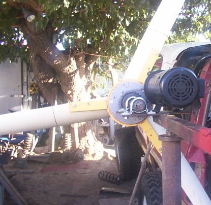
IT FLIES!!!! (if thats the right word for it) and makes some electricity too
A bit out of balance in the blades (It has a slight eccentric wobble at higher speeds) and very heavy to raise alone, but its at the top of a 20 ft section of 2 inch scedule 40 black pipe. It seems to keep its self facing into steady wind as well, and it does yaw and re align its self when wind is choppy. On the down side, I have no choice but to fly it next to a tree, which does obstruct some east winds, my best wind come from the west and its on the west side of the tree, so it should get plenty for my purposes. I had weighed each blade before mounting and all three were within .5 ounces of eachother, maybe that is not close enough? I may shave more off of the heavier blade or try weighting the lighter blades. I have marked the heavy blade, It will rotate (or roll) to the bottom when no wind is present. So far, I have only loaded it with an 1157 automotive tail light bulb and a small 12 volt computer fan, with only the bulb as a load, I saw a high of 13.2 volts but only average of 5.8 volts dc. I am also seeing readings of about 1 amp for every 2 volts generated, I am not sure if this is due to the test load I have chosen, or will that reading have some type of curve as the windspeed increases with a given load ?? I am not seeing the voltages I expected, but have also not had a very windy day yet, so all is not lost on that front, and though it looked as if it were spinning very fast, I am not sure what wind speed or RPM I was seeing yet either. I have just received my high tech laser tachometer from Ebay and will be taking some readings as soon as wind makes its self available for my needs 
I will also try to get a camera and snap another few "in flight" photos soon
What fun it is to just accomplish the goal of lighting a small bulb for a short time, from only the wind, using junk from my yard.
Dodgeman |
||||
| Dodgeman Newbie Joined: 19/07/2008 Location: United StatesPosts: 33 |
Update: Bad News and setbacks I wasn't having much wind last weekend, so I decided to take down the mill for some blade weight adjustments to try and correct the wobble. Everything was going great and I got it down, I had it leaning on a one legged pipe stand I had slapped together for it, and walked into the garage for a moment to grab the plane for the blade adjustment,, when all of a sudden I hear a crash, so knowing it wont be pretty, I go out to inspect the damage. The stand I made held the mill near the top of the tower while tipped sideways, at about 5 feet up from the ground, it held ok from side to side falls, but, in my haste to git-er-done, what I didn't foresee was that it could slip forward (towards the mill head/away from the base) So, needless to say, it fell the 5 feet, and landed right on the face of the blade and busted the home made hub off right where I was worried that it would break in high wind. I suppose that, it is best to find weaknesses while doing back yard testing in low/no wind, rather than in the middle of high wind speed. If, (and its a big if) that hub would have failed/broken in the wind while the blades were spinning at top speed, 20 feet in the air,, (and not due to my own stupidity in dropping it), it would have been possible that I would have had a 9 ft pvc blade flying out in a random direction, which may not have been as much fun. So, needless to say, (but i'll say it anyway) the next one will have to have some small triangular bracing there (at the arrow in the pic) to prevent these setbacks in the future. 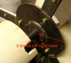
Due to lower than expected voltage output while I did have it flying, I will be gearing my motor with about a 2 to 2.5:1 ratio which I beleive will get my motor RPM up to five or six hundred RPM in good winds, which should get output where I want it. Or I could be wayy off 
DM. |
||||
| Dodgeman Newbie Joined: 19/07/2008 Location: United StatesPosts: 33 |
Ok I made some revisions to my mill, I have rebuilt the hub and converted it to chain drive, it has 24 teeth on the drive gear and 10 teeth on the driven gear (on the motor) for a ratio of 2.4:1, so for every 1 complete revolution of the rotor blades, I will get 2.4 turns of the motor shaft, I am hoping this will get me in the voltage/RPM range which will give me 24+ volts, I will be happy with 15 in a slow wind. I now see how chain drag slows the mill very abruptly when not being spun, like a brake almost, but it spins pretty easily over all, I have yet to get it on a tower, but am assembling it on a stand which allows me to turn it(and run it with a battery which helps with balancing guesswork)
I am considering a furling mechanism, but am unsure how to go about that exactly as yet, Ideas anyone? Here are a few pics of the chain drive converstion 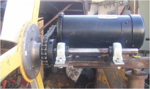
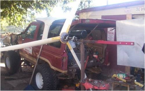
Heres a picture to illustrate the size of this mill (though it looks a little skewed because the truck is behind it, but you can get the idea, {I am in the process of swapping some axles on a bronco 2 so its kinda in the way}, you can see how large the mill is comapred to the vehicle, its not light either (has to be 80 lbs or so)so raising it will be an effort 
I also have to do some tower modifications for some added structural support, I dont think my 2 inch pipe tower will carry this contraption for very long in a strong wind, until its very secured to the ground. I would like 3 inch , but I dont have any yet
Any guesses as to what might happen when I get it in the air? will it generate useable power? will it even spin? will it over spin in high wind? will I only find one more way that "Wont Work". Who knows,,, but I am having fun doing it
All Comments, opinions, assumptions, criticisms, or wild guesses appreciated
|
||||
| oztules Guru Joined: 26/07/2007 Location: AustraliaPosts: 1686 |
Comment: Startup could be a bit difficult, as you need to overcome cogging, and step up ratio, once running (maybe a decent gust), I suspect it could put out some useful power. Opinion: Blade balancing is only useful once installed on the shaft. My blades were not of equal weight, but nor could I guarantee that they would be mounted exactly correctly. Once all bolted up, it is then time to correct any weight distribution changes. I have no wobble now. I added some steel at the front hub disk, and it works very smoothly. Wild guesses: I have no idea, but will look forward to the test results, good bad or indifferent. ..........oztules Village idiot...or... just another hack out of his depth |
||||
asvin bahadur Newbie Joined: 29/07/2008 Location: MauritiusPosts: 21 |
dodgeman, please provide with an update. thank you. asvin.b |
||||
| Dodgeman Newbie Joined: 19/07/2008 Location: United StatesPosts: 33 |
Well here I am again, Windless and wanting, I had some slight breezes which will spin my smaller mills well, but with the friction/reststance of the chain drive assembley on the large mill, It seems to need quite a gust to get it to spin, I have seen it rotate slowly while I was cooking dinner last night, but was unable to get any readings at the time. I am hoping for some bad weather to come but the weather channel is not predicting any for me til next week. Maybe they will be wrong ;) I think I will work on my solar power
|
||||
| asvin bahadur Newbie Joined: 29/07/2008 Location: MauritiusPosts: 21 |
hi Dodgeman, I have a question for you. How much current(DC) did you get when you connected the blades to the motor directly (direct drive)? mine was around 3.2V to 3.4V. i have read somewhere that we can step up the dc current and be able to obtain a higher or double the voltage that we are currently getting. how about having a go a this? thanks asvin.b asvin.b |
||||
| Dodgeman Newbie Joined: 19/07/2008 Location: United StatesPosts: 33 |
Asvin, with the direct drive configuration, (blades bolted to motor) I did see a voltage reading of 13.2 volts DC, that reading was seen during a very strong wind, I connected it to an automotive tail lamp and saw about 1 amp (current draw) for every 2 volts generated, while connected to the light bulb. when the Volt meter was reading 2 volts, the lamp would pull 1 amp, when the volt memter was reading 6 volts, the lamp was drawing 3 amps. I am unsure if that is an acceptable way to test for current, I know of no other way to read current (amps) without a load. Also I do not know what to do with this data other than to convert it to watts (V x A = W) I hope this answers your question. I am still hoping for a gale force wind to happen by while I am home to check my readings, With any luck I will get some wind this weekend. |
||||
| The Back Shed's forum code is written, and hosted, in Australia. | © JAQ Software 2026 |
