
|
|
Forum Index : Windmills : piclog question
| Page 1 of 3 |
|||||
| Author | Message | ||||
martinjsto Senior Member Joined: 09/10/2007 Location: AustraliaPosts: 149 |
hi glenn and thanks for the pic log info, i have just finished the board and have a few questions, sorry if i repeat some already asked. the caps on the diagram shows 0.01uf i ordered some but there completely different to the ones on the photo of the board, mine are quite a bit smaller, is there a perticular type i should of got, the circuit diagram shows them as 0.01uf 63v, are they electro caps or ceramic? also could you please draw a pic for me of the terminal connections as they are on the board, IE bat pos, neg, windmill +, _ inputs, dump and a/c inputs, and serial connections; i have worked out a few but my understanding of electronics is limited and i don't want to damage the board by wiring incorrectly. also on the picture, top l.h.s you can see something attached to the project box and wired to the terminals, it also has a led wired to it, is this a on off switch or something else? thanks for your help with this, it will be great to be able to test the upgrades or sometimes failures to my mill, only real way to tell if im on the right track. martin free power for all McAlinden WA |
||||
CraziestOzzy Senior Member Joined: 11/07/2008 Location: AustraliaPosts: 152 |
Just a quick reply to a question, as no one has provided one yet. Without looking at the photo you mention as a reference, I can assume you should know from the photo if the capacitor is a ceramic or electrolytic type. If you can show me the photo via a link to the URL I could help out more 
Be aware that some modern caps are much smaller than older ones and still maintain the correct voltage and capacitance values. Also, an understanding of the circuit should give you an understanding of the purpose of the capacitor and thus the required type...and also the circuit diagram should indicate the type required...try this link to help you out in understanding electronic bits... HERE is link ...and this one too http://cr4.globalspec.com/member?u=25757 http://www.instructables.com/member/OzzyRoo/ |
||||
| martinjsto Senior Member Joined: 09/10/2007 Location: AustraliaPosts: 149 |
thanks craziestOzzy for the reply the link to the page i am refering to is this http://www.thebackshed.com/windmill/PicLog.asp here is the pic 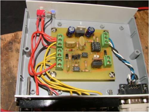
the caps on the diagram are shown as 0.01uf, connected from a pos to neg so i was thinking these are electros but they dont look like them in the pic, i will research the caps more through those links you provided thanks again for the reply martin free power for all McAlinden WA |
||||
| martinjsto Senior Member Joined: 09/10/2007 Location: AustraliaPosts: 149 |
oh i am referring to the beige coloured caps not the blue ones up top of board martin free power for all McAlinden WA |
||||
oztules Guru Joined: 26/07/2007 Location: AustraliaPosts: 1686 |
Martin, the .01 caps look to be there just to keep out the noise. I imagine it makes little difference what breed of capacitor it is as it seems to be mostly a noise attenuator (with a little voltage averaging effect as well). I'm haven't played with pics and am not familiar with the 08 chips, so don't know what their input impedances might be. If very high, then .01 is big deal, and if low impedance then .01 is small beer. Either way different types of .01 caps should make minimal difference here. If truth be known, a fairly wide range of values would make a difference in plotting scatter only. I'm guessing the bigger the value, the less scatter in the results (up to a point) ...........oztules Village idiot...or... just another hack out of his depth |
||||
| CraziestOzzy Senior Member Joined: 11/07/2008 Location: AustraliaPosts: 152 |
Oztules is basically right. I saw straight away from the schematic that the electrolytic capacitors in question filter out frequency noise. The fact that the negative is immediately grounded gives this away, as the circuit is still complete if you were to remove the capacitor completely. The reason for the different shape and/or colour of the capacitor is due more likely to the fact that basically different dialectic materials are used to filter out accurately a specific frequency from the standard "barrel shaped" "blue" ones. You can be assured that if the "beige" coloured capacitors are marked with a +/- symbol that they are of the electrolytic type you need and not the ceramic ones you feared. You can get away with any type of electrolytic capacitor when interpreting a schematic, but be aware that some schematics often specify a particular type of capacitor due to temperature/frequency/current experience in circuit. If the schematic specifies a particular capacitor type, it is not advisable to sway from this. If nothing is mentioned that a certain type of electrolytic capacitor is to be used, then any type in general could be used as long as it has the same values of voltage and capacitance. In summary, some capacitors are very accurate in their ability to filter out a particular frequency range, requiring different materials of construction and creating different shapes and colours to distinguish them from the typical "barrel" cap. The second link I gave you (link) shows the accuracy range as +/- percentage and sensitivity of different types of capacitors to noise filtering. This LINK shows much about the Picaxe chip...I didn't know it uses BASIC...gonna have to grab me one. http://cr4.globalspec.com/member?u=25757 http://www.instructables.com/member/OzzyRoo/ |
||||
Gill Senior Member Joined: 11/11/2006 Location: AustraliaPosts: 669 |
Martin, Glenn has used Greencaps(Polyester or Mylar). Greencaps are not always green by the way. You could just as easily use ceramic. Both are easy to get. I very much doubt you'd find an electrolytic below 0.1uf anyway as the standard range ends at 1uf. It's a great project. Have fun..  was working fine... til the smoke got out. Cheers Gill _Cairns, FNQ |
||||
| martinjsto Senior Member Joined: 09/10/2007 Location: AustraliaPosts: 149 |
thanks for the replyes oztules, craziestozzy and gill, i have finished the board and assembled the unit, seems to test ok but i need a serial cable to connect to pc. i will get one on the weekend so heres hoping for a successful test. the info you posted links to craziestozzy was very helpful thanks i have just finished a anemometer made from old computer power pack fans for the bearing, hub and cage, the bearings are all sealed roller bearings of really good quality and easy to repair, i removed the internal stator and magnets so it spins freely and mounted two new neo magnet pieces inside the hub and opposite each other and then mounted a reed switch underneath. it is very stable and should proove to be reliable. I formed the cups from aluminum sheeting. i think i worked out the wiring connections on the board looking at the top LHS i believe its Bat +, Turbine D/C -, Bat -, the next two are A/C inputs, the bottom two are reed input and i think the last is connected to the bat -, on the RHS from top the first 3 are the serial connections and the botton two are for the relay for the dump load. please advise me if you think this is wrong. thanks again martin free power for all McAlinden WA |
||||
| martinjsto Senior Member Joined: 09/10/2007 Location: AustraliaPosts: 149 |
just got back from the block, unfortunately the test failed i got no input to the computer. i am getting voltage coming out of the serial connections but the software running on the computer is sitting there with "waiting for signal" showing there is no values in the calibrate window. i assume i have the serial wired wrong or the board shorting or a incorrect part. back to the drawing board  on the good side, the anemometer is working really well. on the good side, the anemometer is working really well.
martin free power for all McAlinden WA |
||||
| Gill Senior Member Joined: 11/11/2006 Location: AustraliaPosts: 669 |
G'day Martin, Sounds a little odd, if you've programmed the PicAXE using the programming cable then you've got the wiring right. I'm assuming you haven't modified Glenn's code (if so post a copy so we can check for errors). You can try Programming Editors 'Terminal' programme, accessed from the tool bar under PICAXE. This reads all incoming signals and is not subject to the PicLog format requirement. Try that and see if anything at all is coming through. Did you try for a reading using comm port 1,2,3 & 4? in PicLogs setup? Did you set up the port in Windows Device Manager? That'll do for starters. It'll be something simple I expect. was working fine... til the smoke got out. Cheers Gill _Cairns, FNQ |
||||
| GWatPE Senior Member Joined: 01/09/2006 Location: AustraliaPosts: 2127 |
Hi Martin, I have made a piclog board with good success. I have attached photos below. 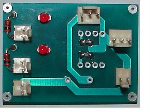
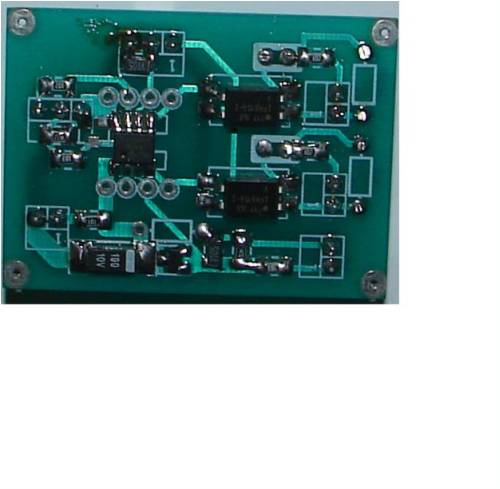
The upper photo is the top side, with the I/O connectors. The lower photo is the component side. I have added input LED indicators for the anemometer and the RPM sensing. The unit is powered from a 5V plugpac, as usually a mains connection is available for the PC logger. The Serial connector is the 3pin one, centre right in the top photo. The components are SMD. The current measurement is for hall effect or shunt in the negative lead. Voltage sensing is scaled to accept up to 65V input. The unit works with Gizmo's code. I have made a plug in LED that I connect accross the serial output connector and ground to test for cct operation. This LED will flash when data is sent. I hope you sort the problems with your unit. Gordon. become more energy aware |
||||
| martinjsto Senior Member Joined: 09/10/2007 Location: AustraliaPosts: 149 |
thanks for the reply gill and gordon, i tried different com ports but no effect, the ports were visible in device manager and had no problems. gill you mentioned programing the picAXE using a editors cable, this is the first time i have played with a picAXE chip set and admit i am a bit clueless about them so i haven't done anything to the chip set at all, i thought once i ran the software on the pc the serial cable will communicate with the chip and set the program up automatically, i am obviously wrong, can i use the serial cable to the pc to program the chip? and how exactly do i do this. is it like flashing a bios on a motherboard? thanks for your help with this, my wife karen is a software engineer i should of asked her about it but then theirs male pride still gotta get the computer to communicate with the chip b4 i can programe it so i was also wondering about the serial db9 on the picAXE, do you use a male or female as i had lots of male to female cables but no female to female (i soldered a male to the serial output wires) and had to swap it for a female to connect to the pc's male serial input.
Gordon your board looks quite simple thanks for your input, i will try to get this one up and working. looks like im the idiot for not realising i have a blank chip from purchase that needs to be programed first thanks again all martin free power for all McAlinden WA |
||||
| Gill Senior Member Joined: 11/11/2006 Location: AustraliaPosts: 669 |
Martin, Yes it sounds like we've got the cause identified so just have to set it up and all will be sweet. The serial download cable is used to programme the picaxe with Glenn's programme. To do this you will need to connect the cable and install 'Programming Editor' on your computer. It is a free download from http://www.rev-ed.co.uk/picaxe/. Perhaps you already have it? Run Programming Editor, and in it open Glenn's file called PicAxe_1.2_Ver2 Logging.bas (or Ver1, as per circuit) and is in the PicAxe Source folder of the PicLog download. Under View in the toolbar, open Options. Set the appropriate settings in each tab. The first two of Mode and Serial Port are essential, the others are as you prefer for convenience. Verify you have Windows Device manager set the com port in question to 4800 baud, 8bit, 1 stop bit, No Parity, No flow control (hardware or software). Now you're all set to load the PicAXE with the programme. Under Picaxe in the toolbar select RUN. If all wiring is correct a progress bar will show the programme downloading to the picaxe. It is a lot like writing a new BIOS. If the wiring is not correct, Programming Editor will report an error. In which case it's time to check all connections. All going well with the download, you must leave the cable connected. First I'd check Programming Editors 'Terminal' (under Picaxe in toolbar). It will show if the Picaxe is sending data to the PC. If so, shut down Terminal and open PicLog. Voil�!! time to play.  was working fine... til the smoke got out. Cheers Gill _Cairns, FNQ |
||||
| martinjsto Senior Member Joined: 09/10/2007 Location: AustraliaPosts: 149 |
thanks for the quick reply gill, yes i have the editor now so i am in the process of re-assembling the unit and installing the program thanks again i will let you know how i get on, oh im using this for my 24v system, the circuit diagram says to change the 22k resistor to a 39k but only one 22k is asterisk, do i change both 22k or only the one on the voltage measurement circuit? martin free power for all McAlinden WA |
||||
| martinjsto Senior Member Joined: 09/10/2007 Location: AustraliaPosts: 149 |
ok i have tryed to programe the chip, when i click run in picaxe tab i get an error saying invalid syntax in line readadc10 4,Volt�and it wont show progress bar you mentioned setting the apropriate settings in mode and serial port tab, is the mode 08m at 4kh? is that all that has to be clicked? or do i indeen have a wiring or voltage due to the resistors problem? martin free power for all McAlinden WA |
||||
| Gill Senior Member Joined: 11/11/2006 Location: AustraliaPosts: 669 |
I've tried it on mine and I'm getting the same thing. I added an extra line after Main: and then the error went to the Amp line. The programme is OK and the syntax is OK too. I think you have just found a glitch in the newer version of Programming Editor. I'll put it to the Picaxe Forum and see what is said. It's a problem out of my league. I'll get back to you on it. was working fine... til the smoke got out. Cheers Gill _Cairns, FNQ |
||||
| Gill Senior Member Joined: 11/11/2006 Location: AustraliaPosts: 669 |
Martin & Glenn, There seems to be a invisible character * after the variable Volt and AMP on the readadc10 line. Delete the blank space after both words and check the syntax again. How can a * be invisible???????????? but it is. Even when opening the file in notepad it is hidden. Most ODD. was working fine... til the smoke got out. Cheers Gill _Cairns, FNQ |
||||
| martinjsto Senior Member Joined: 09/10/2007 Location: AustraliaPosts: 149 |
OK Gill i will try editing the code, it will be good if that is all the problem is, i checked my board again and couldn't fault it. i am having problems with my laptop computer now h/d crashed, had to get another one and have to re-install XP. hopefully i will have it working and setup the software on it. its the one i want to leave running to collect the data whilst i am in Perth, should get 2 weeks worth each visit. i will post my first lot of data, it will be interesting to see the results thanks for your help martin free power for all McAlinden WA |
||||
| Gill Senior Member Joined: 11/11/2006 Location: AustraliaPosts: 669 |
If you have any problems with editing, just do a copy and paste of the code shown on the PicLog page. It is not affected, it is just those in the .zip download. Bloody computers, if it's not one thing it's another. Will listen out for good news. was working fine... til the smoke got out. Cheers Gill _Cairns, FNQ |
||||
| martinjsto Senior Member Joined: 09/10/2007 Location: AustraliaPosts: 149 |
hi gill, well after a long night lasd night still no success. i have the software edited and is working up to the connecting to hardware, i then get an error box stating hardware not found on com1, possable cause 1 hardware not connected, 2 hardware not powered, 3 hardware contains blank microprossesor not pic microprosessor, 4 hardware needs a reset, 5 is pin0 in the programing position with boards fitted with jumpers, i have systematicaly checked firstly the com 1 port by hyperterminal and a loopback cord, it tested fine, 2nd checked pin soldering and config on serial db9 both male and female fine, i then set up board powered with 4.5vdc and did the serial test on the software. volts across pin 8 0v to pin 2 serial input when LED off equal -0.95v when LED clicked on equals -2.87vdc i removed the 39k resistors for the 24v board and replaced with 22k and tested again, same results. i have tryed resetting the picAXE using the method listed no help, i also checked the picAXE chip and its a 12f683 a 08m. i also tryed different chipset settings but didnt help either. i tryed the serial terminal typed in to the output buffer and clicked send but i didnt recieve anything? i am now not sure of my next step, or wether i should scrap this board and start again, i apreciate any help thanks martin free power for all McAlinden WA |
||||
| Page 1 of 3 |
|||||
| The Back Shed's forum code is written, and hosted, in Australia. | © JAQ Software 2026 |
