Notice. New forum software under development. It's going to miss a few functions and look a bit ugly for a while, but I'm working on it full time now as the old forum was too unstable. Couple days, all good. If you notice any issues, please contact me.
pntrbl Newbie Joined: 12/07/2008 Location: United StatesPosts: 32
Posted: 02:53am 25 Jul 2008
Copy link to clipboard
Print this post
1st I'd like to thank all who responded to my posts on the local fire station anemometer. With that being determined unsuitable I'll be needin' to get my own up. Buying one would be too easy and really, it's kinda like building a little windmill, so I'll be making my own ......
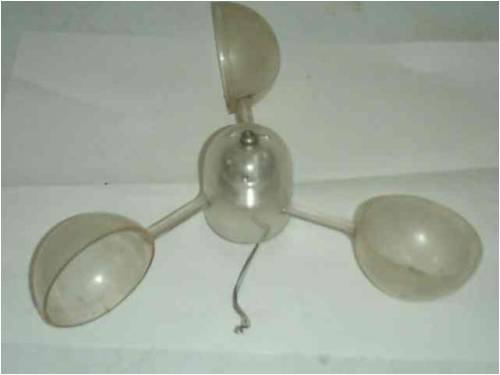
WalMart calls these cups coffee scoopers, I dunno, they sure look like anemometer blades to me!
Bit pricey at $4US ea but they're stainless. Lightweight. I'll bet they'll be flying long after I'm gone ...
Once I get them mounted I'm expecting a 13-14" dia and I'm thinking I'll be able to use the dia. to calculate what rpm I'll see at a given windspeed. Distance divided by circumference over time. I've read this drag type of turbine can't ever have a TSR over 1 and if in fact the TSR is 1, it seems straight forward.
Is it that simple?
SP
Gill Senior Member Joined: 11/11/2006 Location: AustraliaPosts: 669
Posted: 11:11am 25 Jul 2008
Copy link to clipboard
Print this post
G'day SP,
Yes, they look good. I like shiny things. Price staggered me too when I went looking for something suitable. I settled on a set of kiddies plastic juggling balls for about $2 - $3.
I might suggest you reduce the diameter down to about 8 to 9 inches, though it's hard to gauge the coffee scoopers size. Also a lot depends on how many pulses per rev the sensor is going to put out. You'll need to get several pulses per rev. Mine puts out 3 but I'd like twice that many as it makes for greater accuracy in low winds. The smaller the diameter the faster the revs for a given speed. The faster the revs the more pulses and the better the resolution. But if you are building to a plan it might not be a good idea to change it too much.
Have fun... was working fine... til the smoke got out.
Cheers Gill _Cairns, FNQ
pntrbl Newbie Joined: 12/07/2008 Location: United StatesPosts: 32
Posted: 01:36pm 25 Jul 2008
Copy link to clipboard
Print this post
No plans here Gill! It's all seat o' the pants and thank you for your response.
In addition to being shiny the cups are right at 2" in dia. and the whole arm is 7" long. If I use 14" as a dia and if the math is as straight forward as I think, that should be 24rpm in a 1mph wind, which does seem a bit slow. Over 2 seconds for each turn. Hmmm.
Good advice there mate. We'll have to chop 'er down some.
SP
oztules Guru Joined: 26/07/2007 Location: AustraliaPosts: 1686
Posted: 11:18pm 25 Jul 2008
Copy link to clipboard
Print this post
If you can find a way to decrease the drag on the handle it probably would not hurt either... (perhaps replace the flat handle with round rod)
I even wondered if it were possible to put a tight twist in the handle at the cup end and so have the handles edge on to the wind instead of side on.
The width of the handles appear to be about 25% of the ball diameter.
Beautiful looking cups though.
What sort of sender do you intend to drive with the spinner when you get it done.
.....oztulesEdited by oztules 2008-07-27Village idiot...or... just another hack out of his depth
KiwiJohn Guru Joined: 01/12/2005 Location: New ZealandPosts: 691
Posted: 04:30am 26 Jul 2008
Copy link to clipboard
Print this post
I suppose it depends on what you want to use the data for!
A small diameter rotor will respond quicker to gusts, much quicker than your wind generator is ever going manage.
Just a thought.
oztules Guru Joined: 26/07/2007 Location: AustraliaPosts: 1686
Posted: 06:32am 26 Jul 2008
Copy link to clipboard
Print this post
KiwiJohn,
I think it is the mass of the cups and arm assembly compared to the size of the cups that will also determine the dynamics of it. If your keen, you can try and match the mill by changing the weight of the rotor cups and the diameter.
Over here on the bigger grid-tie ones, we use heavy brass cups. This evens out the gusts, and allows the computer to make more reasoned decisions with regard to switching sequences.....(as well as about 13 sec hysteresis) At least that is how it appears to work.
If you were trying to get real time accurate information for some academic reason, then light cups of almost paper weight would give you the best indication.
Diameter is not the only factor determining dynamic behaviour...unless bearing drag or some other mechanical problem exists (iron loss perhaps if you use an iron core in the mix), and then a larger diameter can lend extra torque to mask the mechanical imperfections.
So yes, it is what you intend to use it for that will determine how to best use these interactions.
.........oztulesEdited by oztules 2008-07-27Village idiot...or... just another hack out of his depth
KiwiJohn Guru Joined: 01/12/2005 Location: New ZealandPosts: 691
Posted: 09:01am 26 Jul 2008
Copy link to clipboard
Print this post
With what we have available to us in the way of ultra cheap computing power I expect a sound based anemometer would be even easier than a spinning cup version to make, it would be accurate and very robust. A speaker and a microphone connected to a PC sound card should do the trick quite nicely!
You could get speed and direction from one speaker and two microphones. Mount the speaker at a fixed point and one microphone at a known distance to the north(for instance) and the other at 90 degrees from it and the same distance from the speaker (east for instance). Sound a 'ping' from the speaker and measure the time when the ping is detected at the two microphones.
Just one of those things I might get around to trying one day!
oztules Guru Joined: 26/07/2007 Location: AustraliaPosts: 1686
Posted: 10:18am 26 Jul 2008
Copy link to clipboard
Print this post
KiwiJohn,
Too technically challenging for me I'm afraid.
I like analog, and so if I were to stray to the exotic, I would consider temperature loss between a still air 1 watt heated receptor and a "moving air cooled " 1 watt heated device...... The difference in temp is proportional to the air flow.... mostly coz I think it's simple to implement using simple sensors. (probably even easier in digital dammit)
Actually re-reading the above a whole host of things come to mind that are temperature dependent... including solar cells , leds, diodes, transistors, resistors voltage regulators .... in fact I might just have give it a try now... so the sky is the limit really
An elcheapo anemometer may be only a few components and an op-amp away.
Perhaps passing a known current through a pair of leds or heat dependent resistors (1 in still air and one in moving air stream) and measuring the difference will be enough to work with..balanced bridge, or high gain op amps...........
Curses, now I will have to try and find which of these options will give me the biggest voltage variance for the smallest temperature change..... I can feel another project coming on.
Your digital Doppler version looks way past my ability, but in analog I might be able to get something to move a dial. we just won't know what it means...
hmm a raindrop landing on one sensor, but not the other could scotch this a bit....... but mightn't do the speaker any good either... something more to ponder.
........oztules Edited by oztules 2008-07-27Village idiot...or... just another hack out of his depth
oztules Guru Joined: 26/07/2007 Location: AustraliaPosts: 1686
Posted: 11:35am 26 Jul 2008
Copy link to clipboard
Print this post
Good Grief,
It seems everyone and their pet dog has these already. Most cars have a rough version as a mass meter in the air intakes.
Worse still ... just when you think you have had a half decent idea...... I find this:
This circuit does not look as sexy as those spoons, but is +/- 5% down to 1 foot/min (virtually stagnant air) up to 250 f/min. (1.27 M/S or 4.6 kph or 2.8mph) with the above values.
Just changing values for R1, R2, and R3 takes it up to where ever you want.... sky is the limit.
It is unbelievable that it can measure such tiny air speed so well. Worse still you could build a dozen for a few dollars.
Takes all the fun out of it really
.........oztulesVillage idiot...or... just another hack out of his depth
Dinges Senior Member Joined: 04/01/2008 Location: AlbaniaPosts: 510
Posted: 03:48pm 26 Jul 2008
Copy link to clipboard
Print this post
Oztules, this is how in the past electronic variometers (vertical-speed indicators) for gliders worked: two diodes (extremely tiny ones), one installed behind the other in a moving airstream (between the static and dynamic pressure points). One diode would cool more than the other if the flow of air was in one direction, and the other would cool more if the flow was in reverse.
Dinges chuckles. I figure Oztules's 'simple' is Dinges's 'high-tech'
Sorry, but I knew this was going to happen sooner or later in this thread, with the topic shifting to university-level electronics, PICs, opamps, etc. I find it hilarious that 'el-cheapo' simple anemometers require batteries and opamps...
Me, I'm just a simple dude. More mechanical than electronic. If it can't be solved with a hammer, a welding machine or a lathe I'll have nothing to do with it. Electrickery is dangerous. It kills.
Anyway, this is what I did: I bought a used anemometer vane at a boat trade show. Don't recall the price but I doubt it was more than 1 guilder (ancient obsolete currency; we now have Euros. Price was about 0.50 US$ back then). Installed a simple DC motor in it. Output voltage is then a function of windspeed. All it takes is an analog meter (with a moving needle; anyone remember those ?) and a calibrated scale. Presto. That's what *I* call a simple el-cheapo functional anemometer. Stone-age technology to others, perhaps.
No batteries, no power needed, no opamps, PICs, no logging (I don't need/want logging).
Because of the lousy bearings of that tiny DC motor (which put out about 10 V, so easy to measure) I'm now using a small brushless motor from an old harddisk drive which has ballbearings and doesn't have brushes like the previous motor. It puts out 3-phase voltage, plenty of volts at low RPMs to be easily measurable on a run-of-the-mill analog meter (old VU-meter perhaps ?). The hardest part was making an adapter to mount the anemometer-vane to the motor. Bit of work with the lathe and some work with a file solved that problem.
Ok, now that I've had my 0.02$ worth I'll crawl back under my rock whilst youse continue discussing in a thread that will unavoidably end up in building an 8-channel A/D converter and special-purpose software to log the results.
...they should outlaw all that new-fangled electrickery, if you ask me...
oztules Guru Joined: 26/07/2007 Location: AustraliaPosts: 1686
Posted: 10:46pm 26 Jul 2008
Copy link to clipboard
Print this post
El chuckle chuckle....
Dinges, I notice that while you were banging those rocks together, you managed to take time out to build your own electronic spot welder, (instead of the tried and true method of shorting out a few batteries), a micro-resistance measuring device (rather than using the voltage drop with a fixed current and a slide rule) and a dump load that is more complex than the space shuttle to name but a few.
Nice little anemometer you have there, although I am surprised the purist in you allowed you to use an iron cored design (dc motor), followed by another iron cored drive stator in the disk drive motor... (you won't get to heaven this way.... )
Yes all this digital trickery is above my head, but the simple analog is still very useful.
Actually, looking at that circuit (1 op amp three trannies and a few resistors, it may be quicker and easier to slap it together, than trying to mount the cups on the motor shaft.
I don't know what the thermal lag time would be for this setup, but should get more responsive as the wind speed gets up (this is idle speculation though). I don't know how fast a to92 responds to air flow thermally.
Have fun banging them rocks together up there....
........oztules
ps I won't be surprised to see a Dinges version of this
because he is just as curious as me. Village idiot...or... just another hack out of his depth
pntrbl Newbie Joined: 12/07/2008 Location: United StatesPosts: 32
Posted: 02:06am 27 Jul 2008
Copy link to clipboard
Print this post
In the spirit of finding 14 different ways to do the same thing, I thunked up one of my own.
Years ago I worked on a disc drive that used a magnet in what I think is called a toroidal coil for feedback to the servo loop. This magnet didn't do full rotations but instead tracked back and forth with the heads. The voltage generated in the coil was used for the feedback.
So it occurred to me that if a magnet was spinning in a coil I could use the output for my anemometer. Seems reasonable and simple enough, but what do I know?
I also should admit I'm wanting to wind some wire and pour some resin against the day I build me an air gap generator ...... ya gotta start somewhere!
Here's what I've collected so far;
A 1"x1" neo N50 ring that's magnetized axially. Got a 3/16" hole in the middle for mounting to the shaft.
4 powered iron toroids cuz they had a $10 min. and I figger I'm gonna need some for experimentation anyway. They are also 1" high to match the neo and have a 1.250" ID with 2.00" on the OD. That will leave .125 for an airgap to put wire in.
But this is where I'm stuck. I haven't a clue where to even start with what size and how much wire, and I've also found out them toroids are a blankety blank blank to wind! Ya gotta put the wire thru the center everytime!
So if anybody has a ballpark idea or could possibly point me to some math on the issue, I'll continue pursuing it. Other than that I think I'm just gonna do a hall-effect .....
More good advice from down under on the round arms too. Mounting the flats and getting good perpendicularity at the same time wasn't looking too easy. If I use Alu rod I can slit the end for the cup and thread the other end for the hub. That'll come out straight. Good idea.
SP
KiwiJohn Guru Joined: 01/12/2005 Location: New ZealandPosts: 691
Posted: 02:56am 27 Jul 2008
Copy link to clipboard
Print this post
To be truthful the last anemometer I made used 4 plastic cups of the kind that panty hose used to be packed in many moons ago. The pickup is a simple reed capsule with a magnet on the shaft the output is indicated on a cheap bicycle 'computer'! I have another, improved version, I made with the plastic floats from plumbers 'ball cocks' (aka dunny floats!) but it has never been put outdoors!
With reference to my sonic scheme it is not of course origonal and Vaisala who are one of the big names in professional meteorological devices, use ultra sonic in their top of line wind speed and direction measuring instruments. Incidently, they do not (as far as I know) operate on the Doppler effect which gives an apparent change in frequency when a wave source moves in relation to the observer. Instead they measure the time the wave takes to travel from one known point to another. In my 'design' the ping is passed to the speaker and at the same time passed to the sound card for recording, the output of the microphone is mixed in and examination of the recorded wave will (I presume) show the exact time the sound wave took to travel from the speaker to the microphone.
So the electronics are pretty darn easy if we accept the use of a PC and software is something that only needs to be done once.
Knowing the fixed distance between the microphone and the speaker and knowing the speed of sound in still air we can calculate the expected propogation time. Less time means the wind is blowing towards the microphone and more means the wind is blowing towards the speaker. Using two microphones and a little trig we get wind speed and direction with no moving parts!
Sigh, so many ideas! So little time!
oztules Guru Joined: 26/07/2007 Location: AustraliaPosts: 1686
Posted: 04:50am 27 Jul 2008
Copy link to clipboard
Print this post
Pntrbl,
If I understand you correctly, your magnet is axially orientated.
It would appear that when spun on it's axis, if would not have any changing fields distributed radially. It will not be possible to use this inside a torroid to produce anything as a changing magnetic field will not be present. The top half will be north all the time rotating about it's axis and ditto with the south.
From the torroid's frame of reference, there are no changing magnetic fields available to cut it's coils... ie nothing appears to be happening.
If it were magnetised radially (from the hole in the center to the outside as a two or four pole magnet, you would need only a few turns on the torroid to get something out. N50 1" thick is serious flux,
To successfully use a axially magnetised one, you would need a non-magnetic shaft (brass, stainless etc) and claws like on an auto alt to transfer it to a radial orientation. You would then need only put a coil of wire near it to get some readings to go on with. (The torroid would not then fit around the claws.)
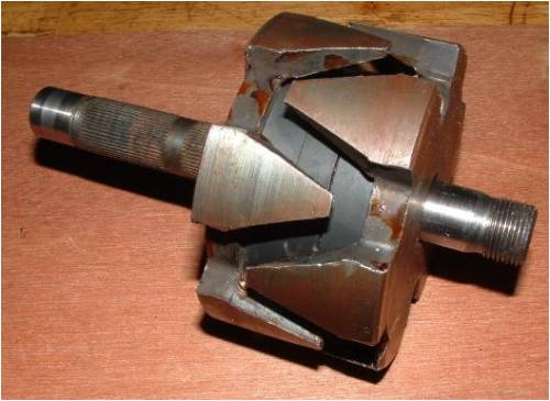
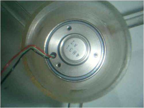
This is a picture from wxyzscience when he did the same thing. At this stage he has not replaced the shaft, but does so shortly as it is pointed out that the flux is getting shortcircuited.
http://www.fieldlines.com/story/2007/7/3/191357/4809
In this instance, the claws set up an alternating pattern of N S N S (however many claw sets there are) So when it spins these fields are constantly changing and cutting the coils around them.
But, steel shaft would short circuit the flux from the north pole to the south pole via itself, and leave very little loose flux to generate anything across the claw gap, as it is easier to make the N to S trip via the steel axle, rather than go out to the claws and jump the air gap.
..........oztules
Edited by oztules 2008-07-28Village idiot...or... just another hack out of his depth
pntrbl Newbie Joined: 12/07/2008 Location: United StatesPosts: 32
Posted: 06:00am 27 Jul 2008
Copy link to clipboard
Print this post
Thank you for your analysis Oz. Seems like I've spent most of my life trying to deny the laws of physics ....
Here's how I thought it would work. Being as the poles are axial the flux lines should be in a radial pattern around the magnet. As the magnet spins wouldn't the flux lines spin with it?
The spinning flux lines would be happy to live in the permeable powdered iron core of the toroid, thereby crossing the winding. The output would be a continuous DC depending upon the speed of the magnet.
But I've been wrong before.
Do the flux lines need to present at 90 degrees to the wires in the coil? Maybe that's what I'm missing ....
SP
oztules Guru Joined: 26/07/2007 Location: AustraliaPosts: 1686
Posted: 06:33am 27 Jul 2008
Copy link to clipboard
Print this post
"The spinning flux lines would be happy to live in the permeable powdered iron core of the toroid, thereby crossing the winding."
But in your scenario, it's all N or S at whatever the flux density at any given point was at the start.
The flux density and pole type remains the same at all points as it spins. No flux change, no voltage generated.....
To generate voltage, the wire must experience a change in flux, the faster the better. Any varying magnetic field will do, but your system changes no field while it rotates about it's axis. so no voltage.
90 degrees is best, but anything away from 90 degrees will be a vector of the angle it is off.
........oztulesEdited by oztules 2008-07-28Village idiot...or... just another hack out of his depth
pntrbl Newbie Joined: 12/07/2008 Location: United StatesPosts: 32
Posted: 02:41pm 27 Jul 2008
Copy link to clipboard
Print this post
Thank you for your patience Oz. You have altered my fundamental understanding of electromagnetism.
That got me thinking ... and digging ....
From Wikipedia;
"This law (in its modern form) states that an electric current is induced in a closed electrical circuit when the magnetic flux enclosed by the circuit changes (in either magnitude or direction)."
I got it now. Once the magnet is established at a steady rpm there is no change in magnitude or direction, hence, no electricity. You're right. It won't work.
That also reconciles what I remember about the magnet in that old disc drive. It never did a full turn but did move (changed the direction) every time the servo moved, which is what created the feedback voltage.
Well, there's one more item on that loooong list of things I thought of that didn't work! Thanx again and I'll be moving on to Plan B .....


 dammit)

 ... but mightn't do the speaker any good either... something more to ponder.


 )
)