
|
|
Forum Index : Windmills : need to increase voltage
| Author | Message | ||||
| adric22 Regular Member Joined: 06/08/2008 Location: United StatesPosts: 47 |
I have a permanent magnet brushless 3-phase motor I want to use for my windmill. Unfortunatly, when I spin it by hand at approx 200 rpm, I only get about 1.5 volts. So, I figure I have these options available:
It seems all of these have some kind of disadvantage, but I'm leaning towards rewinding the motor. My main issue is that I do not know exactly how many more turns it needs to get up to the voltage I need to charge a 12V battery. Is there a specific ratio of turns to volts? Can I just count the number of turns it has now and use a standard ratio forumla to determine the number of turns it needs for the higher voltage? |
||||
| KiwiJohn Guru Joined: 01/12/2005 Location: New ZealandPosts: 691 |
Yes, double the number of turns an you will see double the volts though in your case it looks like you need 10 times the turns. |
||||
vawtman Senior Member Joined: 14/09/2006 Location: United StatesPosts: 146 |
Not a good choice of motor.Sorry 
Search on and have fun. |
||||
| Dinges Senior Member Joined: 04/01/2008 Location: AlbaniaPosts: 510 |
Adric22, If the 1.5V you get out of it is AC, and the genny is 3-phase, you can wire it in star (if it's not yet wired in star, that is). That would give you an output voltage of 1.5Vac * 1.73 = 2.6 Vac. Now if you'd rectify the 3-phase AC to DC you'd get another increase in voltage, by a factor 1.41 this time: 2.6Vac * 1.41 = 3.67 Vdc. This 3.67Vdc is still much less than your needed 12Vdc (nominal). So you could rewind, with a turns ratio of somewhere around 12/3.67 = 3.4. You'll need about 3.4 times as many turns per coil as you have now. You give practically no information about the motor/generator (size, name plate date, power, etc.) so it's hard to guess what kind of motor you really have there. It could be a 0.1 W floppydrive motor or a 1000 W brushless servomotor, or anything in between. It'd be a waste of effort to rewind the 0.1W floppydrive motor if you want practical power (though technically very well possible to do). A bit more information, for example nameplate data, one or two pictures of the victim, etc. could really help people in this forum who want to answer your question but aren't supplied with much information to base their help on. Edit: the above winding ratio (factor 3.4) is based on my assumption that you would want the motor to cut-in at 200 RPM. It depends on the size of the motor and blades whether that is realistic or not; for a tiny genny it likely isn't. |
||||
| adric22 Regular Member Joined: 06/08/2008 Location: United StatesPosts: 47 |
Okay.. I'll give you all the information you want.. Here is the picture of the motor before any modification: 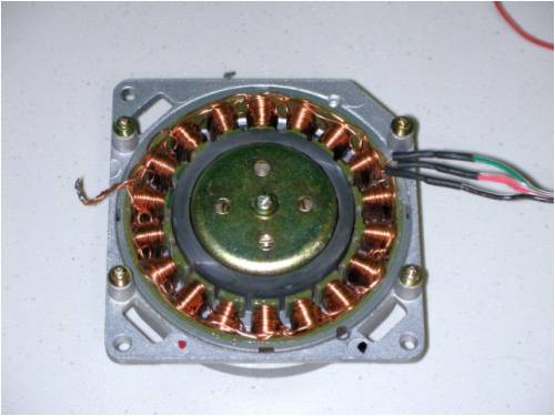
This thing came out of an old DLT tape backup drive. Actually, I got two identical ones out of the drive. The size of the motor is about 3.5 inches diameter and about 0.75 inches thick. yes, I am aware this won't produce an enormous amount of power. What I'm wanting to do is build a small wind generator first (maybe 4 feet in diameter) as a learning experience and so that I can experiment with different types of blades and fabrication techniques. Once I'm satisfied, I'll move on to building a much larger one. I have taken the motor apart and I have started to unwind it keeping track of how it is wound. I was actually surprised to learn how it was wound. There are 32-turns on each pole. It doesn't really make sense to me. It has 18 poles and I would have always imagined that the 3-phase system would have been wound like 1-2-3-1-2-3-1-2-3, etc.. But it is actually like this: 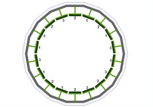
They aren't spaced exactly even which I thought they would be. Would there be any advantage to re-winding them 1-2-3-1-2-3, etc? I found some magnet wire at Radioshack yesterday evening but the spool was so small I don't think it is long enough to give me 320 turns per pole. I'll need to buy a spool from the internet. So anyway, I plan to wind this thing back up in whatever arraingment makes it best suited for generating electricity for charging a 12V battery (so around 15V to 16V, I would think) As for the person who said this motor isn't suitable. Well, I think the size is perfect, and the re-winding will be a learning experience for me which is what I wanted. So I think it is a suitable choice. I just need to figure out what I'm doing. |
||||
| Dinges Senior Member Joined: 04/01/2008 Location: AlbaniaPosts: 510 |
I tend to agree with Vawtman that the motor isn't suitable if you want to produce useful amounts of power, but if you want to just play around, learn and experiment it'll do fine. I have in the past seriously considered experimenting with a similar motor myself. Vawtman prefers to spend time experimenting with VAWT windturbines that others consider to be unsuitable. That doesn't stop him though.  Neither should his remark stop you from doing what you think is best in your situation. You're the only one who can judge your skills, time, interests, desires and how to spend your resources on them. Neither should his remark stop you from doing what you think is best in your situation. You're the only one who can judge your skills, time, interests, desires and how to spend your resources on them.
I hope you haven't progressed too far with unwinding yet. I was going to tell you to make very good notes of the order of the coils (1-2-1-... in your case) AND the winding direction of them. It's possible (in fact, likely) that different coils within a phase (say, phase 1) are wound in different directions; some clockwise (CW), others counter-clockwise (CCW). The reason they may use different winding directions is because of the number of magnetic poles on the rotor (in your previous post you said 'it has 18 poles' but that's incorrect, you have 18 stator slots. The number of magnetic poles on the rotor could be (and most likely is) different from this number). If you haven't kept track of the winding direction not all is lost yet. You'd have to find out how many magnetic poles there are on the permanent magnet (PM) rotor. You can do this by taking a small magnet and moving it past the rotor. You'll feel areas where the magnet is attracted and where it is repulsed, with little 'humps' in between where no field is felt. I usually draw a little mark on the rotor there. Go around the entire rotor like that with a small magnet, and then count the number of poles. Then, go to this site (German, but very good; use an online translator if your German is underdeveloped): http://www.powercroco.de/ This site has a LOT of information about rewinding and modifiying motors like yours. You could easily spend a week reading it all. BTW, notice these guys take tiny motors like yours and turn it into 1+kW motors. Just to give an idea what the possibilities can be (though you won't be able to turn it into a 1kW generator; a 1kW motor (for a few seconds) would work though). Check out the 'construction' part, and the 'combinationstable'. Enter the number of magnetic poles of the rotor (that you determined above with the help of a little magnet) and stator slots in the calculator at the top (nuten=slots; pole=poles): http://www.powercroco.de/Kombinationstabelle.html The output will be something like aBAbCc... etc., where a small 'a' means 'phase a wound cw', capital A 'phase a wound CCW', b = phase b wound cw, etc. This page gives an excellent explanation: http://www.powercroco.de/schemalesen.html With that information you can proceed to rewind. Note the above step is only needed if you have neglected to gather the winding-direction information as you unwound the stator. If you did collect that info, just follow your notes and rewind exactly the same but with more turns per coil. As for the turns per coil; I said in my original reply that you could multiply by 1.73 if you'd wire the 3-phase genny in star. However, from your photo it's obvious that the motor/generator is already wired in star (the star point is on the left in this photo: 
Notice the point where the 3 phases are connected together; this is the star point. So if you want this generator to cut-in at 12V you'd need to rewind with about 6 times as many turns (1.5Vac *1.41 = 2.1Vdc; turns ratio = 12Vdc/2.1Vdc = ~6) The above is if you want it to cut-in at 200 RPM, which sounds very slow for a genny that size to me. Others are likely in a better position to judge this than I though. 300-400 RPM for such a tiny genny is more suitable, I'd guess. If you'd want it to generate 12V at 300 RPM, you'd have to increase the number of turns by a factor 4. If you'd want 12V at 400 RPM, increase turns by a factor 3. You'll likely also have to use thinner wire than original to make it all fit in the same space. If you go for 4 times the number of turns your wire diameter should be halved. The longer wire (4 times as long) and thinner wire (1/4 the area) will increase the internal resistance of this genny a lot (roughly by a factor 16). The rotor likely has ceramic magnets, not neodymium ones. That puts another limit on the power it can produce. As said before, this generator will never be a powerhouse. Don't expect too much and you won't be disappointed. |
||||
| adric22 Regular Member Joined: 06/08/2008 Location: United StatesPosts: 47 |
Thank you for the detailed reply. Unfortunately, I have already removed all of the windings and as you guessed, I did not pay attention to the direction of the windings. However, I still have another, identical motor, that I have not yet disassmbled. So either way, I should be able to find out how it is done. I realized that the motor wouldn't give me much power because of its small size. But it sounds as if you are telling me that another motor of similar size may be able to give me a lot more power than this one. If so, that is the direction I need to go. I want to have it as efficient as possible in a 4-foot diameter turbine so I'll have accurate numbers to compare to when I build a larger one (which will be using the most efficient motor I can buy/build.) Any suggestions on where to find a suitable motor in this size range? |
||||
| Dinges Senior Member Joined: 04/01/2008 Location: AlbaniaPosts: 510 |
Maybe you could check but I *think* your rotor has 10 magnetic poles; when I enter that number (18 stator slots, 10 magnetic poles) into the calculator (http://www.powercroco.de/Kombinationstabelle.html) I get a winding scheme similar to yours: ABabcBCAcabABCbcaC (with A=2; B=1; C=3). Maybe you can verify if the rotor has 10 magnetic poles, if so, you wouldn't need to take the 2nd motor apart. Not sure if other motors of similar size will be better suited; I can't think of any, at least. I'm working on a 1.3-1.5 m turbine of about 100W and its size is substantially larger than your motor ( http://www.anotherpower.com/gallery/album69/blue_boy_stator_ gutted) A F&P looks actually quite a bit like the larger brother of your motor. Plenty of information on this board on using F&Ps. Pity they're a bit uncommon outside of Australia and New-Zealand. |
||||
| Dinges Senior Member Joined: 04/01/2008 Location: AlbaniaPosts: 510 |
Hm. When I enter 8 magnetic poles (18/8) I get another winding scheme that is different from the 18/10 scheme but ALSO exactly fits your pattern: AbaBcbCacAbaBcbCac (again with A=2; B=1; C=3). It has the exact same order as the 18/10 scheme in my previous post but differs in the winding direction (CW/CCW) of some coils. So your rotor might just as well be an 8 pole. Safest way would be carefully to count the number of poles on the rotor and continue from there. Or unwind the other motor as you planned. Sorry for the confusion. |
||||
| adric22 Regular Member Joined: 06/08/2008 Location: United StatesPosts: 47 |
Well, I will probably do that when I get home just so I'll know. But I think you've convinced me not to use this motor. After all, I suspected it would take me many hours to re-wind the thing. It would be worth it if the results were a fantastic working generator in a small package. But, it sounds like it is a lost cause. I've looked at some treadmill motors on ebay but if I look at the RPM and the voltage, the math shows that I'd only get about 6 or 7 volts at 300 to 400 RPM. Still not enough. So I'd probably have to re-wind one of those as well. |
||||
oztules Guru Joined: 26/07/2007 Location: AustraliaPosts: 1686 |
There will probably be not much use trying to aim for less than 400rpm cutin. The amount of power available is barely worthwile trying to get anything below 400 with a 1.2m prop. This will ease the rewind a bit, and maybe avoid stalling the little blades when some wind does come along. Starting the blades in less than 10mph (around the 400+ rpm) even still may be a problem as the start torque will be only 10grams/meter. Whether this overcomes the cogging I don't know, but hopefully a gust probably will. .........oztules Village idiot...or... just another hack out of his depth |
||||
| adric22 Regular Member Joined: 06/08/2008 Location: United StatesPosts: 47 |
Okay.. Got home and counted the poles. I did it twice just to make sure. There are 8. |
||||
| pntrbl Newbie Joined: 12/07/2008 Location: United StatesPosts: 32 |
Under the "things you learn" category, I too would have thought a 3 phase set up would have the coils in a 1-2-3 pattern. Seems intuitive .... but apparently not! There is a recognizable pattern in the 18 coils tho. 18 coils/3 phases means 6 coils per phase. The 6 are split into 2 sets of 3, which are diametrically opposed, and the middle coil is wound opposite in every set. That makes me feel better somehow! LOL! How the timing could possibly work with 8 or 10 poles, or 42 for that matter, makes no sense to me at all, but I'll keep lurking along and learning .... SP |
||||
| Dinges Senior Member Joined: 04/01/2008 Location: AlbaniaPosts: 510 |
I find it really helps to draw these things out: 
Take a look at a single phase, e.g. phase 'a/A'. Notice how, at both the 12 o'clock and 6 o'clock position, the stator tooth is close to a N-pole on the rotor. Call this 'A' (capital A, wound CW). Now have a look at the 'a' at 2 o'clock, 5 o'clock, 7 o'clock and 10 o'clock. These are instead seeing a S-pole of the rotor and thus are wound in the opposite direction, hence 'a', CCW wound. The same goes for phases b/B and c/C. There's actually some logic in there...  and it becomes much more understandable if you make a quick sketch of it. and it becomes much more understandable if you make a quick sketch of it.
I must admit these are a bit complicated examples with strange winding schemes. In practice we can often wind ABCABCABC (or 1-2-3-1-2-3) because we choose a pole number that's a sub-multiple of the number of stator slots. E.g. in the case of a 'normal' motorconversion with 36 stator slots and a 12-pole rotor the winding scheme is a very straightforward 1-2-3-1-2-3, with all coils wound in the same direction and following eachother in strict order. Besides, in 'normal' motorconversions coils span several slots, unlike in the example of the original poster where each coil is exactly one slot wide. Confusing ? Naah....  |
||||
| adric22 Regular Member Joined: 06/08/2008 Location: United StatesPosts: 47 |
That is a nice CAD drawing, what did you make that in? I made the other one up above in Google Sketchup. Adding the magnets with their poles in the picture does clear things up a little bit. I may still rewind this one just for the educational experience. Anyone know where I can buy some magnet wire? I went to Radioshack and bought some, but the spool is so small that I could probably only make one or two coils with it. Being that I have to coil at least 6 stators at a time. I suppose I could solder spools together and coat them with something (maybe even heatshrink) but I'd rather have a bigger spool. I checked all the local hardware stores and even Fry's electronics and found nothing. I guess I'll have to order online and wait a week or two. |
||||
| pntrbl Newbie Joined: 12/07/2008 Location: United StatesPosts: 32 |
1st I'd like to agree with adric22 that that is a fine CAD drawing Dinges, and then add my personal Thanx for taking the time. A sketch makes what's happening in there abundantly clear. I think it's starting to sink in now ...... SP |
||||
| Dinges Senior Member Joined: 04/01/2008 Location: AlbaniaPosts: 510 |
Your stator seems to be quite a big thicker than the similar motors I've played with. If it were mine I would definitely give it a go rewinding, it shouldn't take too much time and effort. The genny should be able to put out a few watts (5-10W?) at least. Probably it'll work much better than the small stepper I've played with in the past. For wire, try to find a motor rewind shop in your area. That's where I get my wire from, their left-overs on the spools (too little for them to use so they normally throw it away). If you take the motor with you and show them what you plan to do with the wire (and that you don't intend to compete with their business) they may just give you some or sell for very little. Try to talk to the chef of the shopfloor, not the people in the office. |
||||
| The Back Shed's forum code is written, and hosted, in Australia. | © JAQ Software 2026 |
