
|
|
Forum Index : Windmills : motorconversion efficiency measurement
| Page 1 of 2 |
|||||
| Author | Message | ||||
| Dinges Senior Member Joined: 04/01/2008 Location: AlbaniaPosts: 510 |
All this talk lately of efficiency made me curious as to how efficient my 500W motorconversion 'blue boy' actually is. I decided to measure it. For completeness' sake I'll include all measurement steps so others can easily repeat it for their generator if they desire to do so. The 'math' part below can be skipped if you're only interested in the results. To determine generator efficiency we need to know both the mechanical input power and the electrical output power. Electrical power is easy to measure using a voltmeter and amp-meter as the genny is charging the battery. Mechanical power isn't much harder to determine using a De Prony brake. Below is a photo of the setup I used. 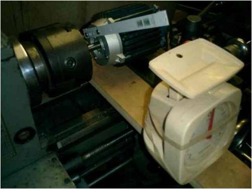
The lathe was used to supply mechanical input power to the conversion. The generator shaft is clamped in the chuck. The house is more or less free to rotate but actual amount of rotation is held in check by an arm (with measured length l). The end of the arm presses against a weighing scale. The 'weight' on the scale is an indication of torque, which can be used to determine mechanical input power, with the exact relationship being: ----------------------- [START THEORY; skip if desired] P=T*omega where omega = 2*pi*f and f=n/60 (frequency = RPM/60) so P = T * 2 * pi * f = T * 2 * pi * n / 60 P = T * pi * n / 30 and T = F * l (T = torque [Nm]; F = force [N]; l = arm length [m]) where F = 10 * 'kg' So mechanical input power is P = 10 * 'kg' * l * pi * n / 30 which reduces to P = 1.05 * 'kg' * l * n So, the mechanical input power P can be determined by measuring 'kg', length of arm 'l' (a constant, 0.21 m in my case) and n (RPM) as it is charging a battery. We can determine electrical power output by measuring both voltage and current. Keep in mind that my measurements were made with non-RMS meters, so there may be an error because of this due to the non-sinuso�dal nature of the charging current. Efficiency of a generator is defined as: eff = inputpower/outputpower. If we know both electrical power out (volt & amp meters) and mechanical power in (determined with the De Prony brake) we can calculate efficiency. [END THEORY] ------------------ Below is the graph that shows both mechanical input power and electrical output power as a function of RPM, with power (W) being on the left scale. The downsloping curve is the efficiency curve, with the horizontal line being defined as 100% efficiency (chosen so that 100W on the left equals 100%) 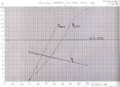
(high-resolution images can be found here: http://picasaweb.google.com/motorconversion/500WMotorconvers ionBlueBoy (click on the magnifying glass to zoom in)) To my surprize, efficiency in the lower output range was actually quite high; at 3.8W electrical power into the battery efficiency was 72%. This figure takes into account ALL losses in the system, also rectifier losses, so the actual efficiency of just the generator would be even slightly higher. As output power goes up efficiency goes down, as expected because of I^2*R copper losses. I rate this generator at about 100W maximum (even though it originally was a 500W motor). At full rated output power efficiency is about 50%, which isn't fantastic in my opinion. The losses consist of all losses in the conversion chain: bearing losses, iron losses in the stator, copper losses in the stator, wire losses to the battery and rectification losses in the 3-phase rectifier. So it includes more than just the generator losses. Power lost in the rectifier is about P = sqrt (3) * 1.5V * I so definitely not negligeable. As there may be non-linear losses involved (losses that vary non-linearly with RPM) I decided not to calculate 'the' efficiency but rather establish an efficiency curve over the operating range of speeds. One more note; after the testruns the generator was noticeably warmer, I estimate it was at about 45 deg. C. So was the rectifier. Of course, the power losses had to go *somewhere*, in this case being used to heat the generator, rectifier and connecting wires. At some point there was 470W being put into the genny and 176W extracted, so the difference (~300W) had to go somewhere... All in all this is a pretty simple measurement technique to determine generator efficiency, which yields a lot of information about the performance of the generator. It would be nice to see more of this kind of data in the future from other people's gennies, as it provides a yard stick to help evaluate performance of generators. |
||||
| GWatPE Senior Member Joined: 01/09/2006 Location: AustraliaPosts: 2127 |
Hi dinges, I did not use a lathe to spin my alternator. I used one winding. I had a pair of hall effect rotor positioning sensors. These controlled an electronic switch that pulsed current into the coil at the correct timing. This was connected to a DC power supply with RMS voltage and current sensing. One of the other windings had a resistive load applied. The RMS voltage developed across this resistor was measured and confirmed with a CRO. There were two unused windings in my case. I measured power in and power out at various input voltages. The fixed pulsewidth gave a varying rotor speed with input voltage. The efficiency was close to unity. This was 15years ago when attempting to get over unity was the go. The resistance of the load was over 100x the windings resistance. I do not intend to repeat this exercise, but others with ironless axial flux alternators may be able to reduce the air gap and modify the coil shape for square waves and confirm on a setup like yours. I remember performing electrical efficiency testing of all sorts of motors in an electrical engineering module at Uni. All these systems had an iron core, including DC, AC induction and AC synchronous all had efficiencies below 90%. The AC synchronous was about Max. 88%, the DC about Max. 85% and the AC induction was about Max. 70%. This was at about the 500W power level. This was over 30years ago, but the engineering hasn't changed much. This was why I explored permanent magnet ironless designs in my research. Gordon. become more energy aware |
||||
oztules Guru Joined: 26/07/2007 Location: AustraliaPosts: 1686 |
What voltage battery was it running, and can you change the voltage up (from 12 to 24 etc, and see what happens to your efficiency at the same kinds of rpm.... More importantly, did you happen to get a power/rpm of the iron loss only (no batts connected) ..........oztules Village idiot...or... just another hack out of his depth |
||||
| GWatPE Senior Member Joined: 01/09/2006 Location: AustraliaPosts: 2127 |
Hi dinges, I have seen some of the photos of the conversion. The wire is very thick. It seems as though this was a 12V test. I would say from the graphs above that the iron loss is the culprit. I would expect that this conversion would have a maximum useful rpm of around 400rpm. this would suggest to me that the test was at too high a voltage. What if the test was repeated with a 6V battery? Gordon. become more energy aware |
||||
| Dinges Senior Member Joined: 04/01/2008 Location: AlbaniaPosts: 510 |
Oztules, I should have mentioned in the original post, but test system voltage was 12V. This genny was rewound to have a 12V cut-in (star) at 250 RPM. I have no intention of running this generator at anything else than 12V. Cut-in would be too high for 24V (~500 RPM) and too low for 6V (~125 RPM). I haven't tested for other battery voltages as there's no direct need for this data and (practically too) because I don't have the required batteries for such a test. The goal here was mainly to get a handle on generator efficiency for blade design purposes. Wasn't supposed to be a full-blown test, just something I could quickly do before going to bed yesterday evening... But it seems to have whet your (& my) appetite... I'll try to run another series of tests with the generator unloaded today to figure out the combined iron+bearing losses. Gordon, the generator was wound with 0.71mm copper wire; the resistance per phase is 1.38 ohm. What's your reasoning behind 400 RPM being the maximum useful RPM ? |
||||
| Dinges Senior Member Joined: 04/01/2008 Location: AlbaniaPosts: 510 |
Just tried to remeasure just the iron+bearing losses but couldn't. Turned out the force was so little any imbalance in the motor case would upset the torque measurement (just slightly shifting the powercord would change all values). I did however try to calculate iron+bearing losses, by subtracting from the total losses the copper losses (P=I^2*R) and rectifier losses. Turns out that the combined iron+bearing losses are scattered around 9-13%. Assuming each (new) bearing has a loss of about 1% that leads to 7-11% iron loss. Much lower than I expected. The copper losses are the bulk of loss in this generator. That suggests there is too little magnetic flux in this conversion, even though I stuffed it to the brim with magnets. The filling factor of the round magnets is however worse than could have been obtained with rectangular magnets, and the relatively large airgap (1.5mm at the middle of a magnet) isn't helping much either. I did make a graph of the generator efficiency, this time excluding rectifier losses. Rectifier losses *do* matter in the entire windgenerating system, but shouldn't be included in the generator losses, so I separated the two now. 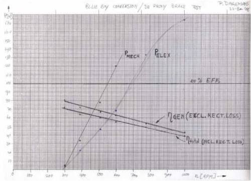
(high resolution image here: http://picasaweb.google.com/motorconversion/500WMotorconvers ionBlueBoy/photo#5237671013160885154 ) As can be seen, maximum generator efficiency is about 80% at the lower range, decreasing to about 60% at its rated 100W output power. Most of the loss is copper loss, with rectifier loss and iron loss being of lesser importance: at 1000 RPM there was about 46W iron loss (10% of 468W mechanical input power), 16W rectifier losses and 210 W copper losses). I'm pleasantly surprized by the generator efficiency at the lower end of the power range, I would have expected it to be worse. 70%-80% I consider to be acceptable for a motorconversion. But the fact that the iron losses are so low compared to the copper losses suggests this generator is 'undermagnetized', despite my attempts to cram as much magnet as possible in there. Most likely it's caused by the relatively large airgap. This was a deliberate design consideration but, as can be seen, comes at a price: acceptable efficiency in the lower power range but rapidly increasing copper losses as power goes up. |
||||
| oztules Guru Joined: 26/07/2007 Location: AustraliaPosts: 1686 |
Depending on the curves... If iron loss is the major player, then maybe bigger prop. Less rpm to keep the losses lower from the iron, and more power to drive it.... and let me see.... oh yes a booster... 
If copper loss is greater, then make it a 24v system, so less current per watt,.... and goodness me, a perfect candidate for..... a booster??? 
He he he, yet another possible project I can see for the poor suffering denizen of the North. 
........spoke to Ronb today.... he renewed my evil streak.... can you tell? .........oztules Village idiot...or... just another hack out of his depth |
||||
| oztules Guru Joined: 26/07/2007 Location: AustraliaPosts: 1686 |
You posted your post while I was writing mine... I've been out flanked. You know I can't not say .... resistance resi... nah, even a Dutchman doesn't deserve that. But it does underline the thrust of what I was saying. Get the resistance to the absolute minimum and the rest of the design will have to have been good... by necessity it looks after itself. nuf said. Thanks for doing that test, It showed us both something I think. If I read your Femm correctly on Picasa, this was in saturation already...., I think you would have done better with a bit (he actually means a lot) more flux yet, if you are to balance the copper and iron loss. In truth, I think you were beaten by diameter. ........oztules (oztules doodles in sand with finger wondering what Dinges booster will look like) Village idiot...or... just another hack out of his depth |
||||
| Dinges Senior Member Joined: 04/01/2008 Location: AlbaniaPosts: 510 |
"If you only have a hammer, you tend to see every problem as a nail." These wise words from Maslow came to mind as I read your reply. No idea why. On a more serious note: if you have a decent design/schematic then throw it in the group and I may give it a go sooner or later (more likely later than sooner). |
||||
| oztules Guru Joined: 26/07/2007 Location: AustraliaPosts: 1686 |
Ok, that one by flux looks to be a perfect candidate for that size project you have there. At 24v 1000rpm, your new losses will be Diodes=8W (from 16w before) Iron loss 46W, same as before. Copper loss 52W (from 210w before) 8.7A to 4.35A w=IxI xR= 4.35x4.35 x2.76=52W. power into batteries is (emf-batt)sq /r So 48-24sq/2.76= 24sq/2.76= 208.6watts I make it about 200 watts into 24v battery for about 100w losses. Input power should be about 300w, output 200w losses 100w. In reality state of charge changes this a bit, but a ball park estimate should give some guidance. The losses will be less in reality as SOC will likely range from 22v (worse) to 29v (best) EMF will remain the same. but EMF-SOC will change as charging goes up. nuf waffle. And wait for it.... copper loss = iron loss (close enough) ............oztules (wanders down the street singing "...if I had a hammer, I'd hammer in the morning, I'd ha.....) Village idiot...or... just another hack out of his depth |
||||
| GWatPE Senior Member Joined: 01/09/2006 Location: AustraliaPosts: 2127 |
Hi dinges, I would say that the power to be dissipated would quickly raise the temperature of the machine to a level where there could be permanent damage to the permanent magnets.. You might be interested that the wire in my machine is 0.18sqmm and each winding has a resistance of 0.8ohms. Each winding passes a max 4A and there are 4 windings. My machine dissipates a measured 65W in the stator at the 450W maximum power level. This equates to only 87% efficiency. The efficiency increases to 93% at the 100W level, a level where the mill spends a lot of time. I have to accept an additional 13W loss as well in the schottky diode rectifier at 450W. The maximiser adds an extra 6W loss at the 100W level and 9W at the 200W level. Maximum losses are at maximum power. System efficiency is maximum at 24W, but I consider this relatively unimportant. The conversion approach is one we all have to do. I made one years ago using Samarium-Cobalt blocks. Only 2 pole pair rotor though. I had no success with it. Gordon. become more energy aware |
||||
| Dinges Senior Member Joined: 04/01/2008 Location: AlbaniaPosts: 510 |
Oztules, I'll try to find Flux's design and see if it's doable to build. Likely it won't be used with this genny though. I didn't go through all the work of a rewind to *still* need fancy electrickery to match the genny to the battery...
Gordon, remember, I was putting nearly 500W mechanical energy in that small motor for about 5-10 minutes and it had only become lukewarm. I find that pretty good results. In a real-world situation there would also be the convective cooling from the wind. Not sure why you had no succes with it, but 2 poles is very little so would become a fast genny that would need many turns of thin wire to generate the needed voltage. Maybe you also used the original (high-resistance, high-voltage) motor windings ? My main preference for conversions is because of their mechanical robustness, I consider reliability more important than super-high efficiency (being able to harvest the smallest breeze). Safety comes 1st, reliability 2nd, output 3rd. Their lower efficiency (due to iron losses) is a downside that comes with it. Still an acceptable trade-off, I think, considering the rate at which I see axial fluxes fail. (in the AF's defence, most failures seem to be caused by sloppy construction or running it far above its ratings) |
||||
| oztules Guru Joined: 26/07/2007 Location: AustraliaPosts: 1686 |
edit Didn't come out too well here... If I get time I will draw it out better for you .........oztules Village idiot...or... just another hack out of his depth |
||||
| GWatPE Senior Member Joined: 01/09/2006 Location: AustraliaPosts: 2127 |
Hi dinges, this was not for a windmill, but for a brushless DC motor for a solar car application. I challenge the mechanical robustness of an axial flux design machine you mention. My axial flux altenator has a closed external construction. The rotor is supported on 90mm OD bearings each end. The stationery inner shaft bearing dia is 65mm. The designs provided by DanB and Piggot etc are simplistic, but considering where they were intended to be made and used, they are doable. I hope to publish more photos of my setup. Gordon. become more energy aware |
||||
| Dinges Senior Member Joined: 04/01/2008 Location: AlbaniaPosts: 510 |
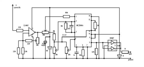
Thanks Oztules. The schematic looks familiar (I've seen it before) but is unfortunately illegible. And I don't see any inductors or capacitors that function as charge storage for the boosting, or any big transistors/FETs ? Gordon, This is the 2nd time you're arousing my curiosity with that generator of yours . Did you construct yours perhaps like mine (with attachment of the two rotors at the outside circumference) ?
http://www.anotherpower.com/gallery/album46?page=1 If one builds it like that it becomes much simpler to enclose the rotor and generator and protect it from the environment. I don't live in Colorado but in NL, not too far from the sea (nearest salt water is about 10 km off). And then there's the rain... But fortunately the summer is about to end so the raining should stop... 
Peter (who recalls having seen the sun once, long ago). |
||||
| GWatPE Senior Member Joined: 01/09/2006 Location: AustraliaPosts: 2127 |
Hi dinges, My alternator is unlike any commercial unit, and unlike yours[I think yours is made from acrylic]. My alternator if fully encased in solid high tensile aluminium, 12.5mm thick. The magnets are strong enough to dish the outer plates. One 10mm thick soft iron magnet return path ring is bolted to each of the aluminium plates with 22 x 3/16" cap screws. The 11 x 1/4" cap screws around the perimeter are required to straighten the plates, so a solid aluminium 2 part spacer ring keeps the plates apart. The 3mm air gap presents many mechanical problems. I had to make special tools to allow safe assembly and any future servicing. I live only 500m from the southern ocean. A lot of the weather comes from the south-west associated with sometimes 4-6m ocean swell and 30knot winds. The mill had to be pretty well sealed, without introducing friction. I am fortunate that there is little heat produced in the stator. This is a result of very little, thin stator wire, and still low resistance. You probably thought the 3W/gram of wire at max output was a typo. It is so long ago that I made the alternator and without any drawings. All components bolt together, and the entire unit can be disassembled. I have said before that I used an empirical iterative process with a prototype to find optimum wire sizes and coil dimensions and magnet spacing, etc. I worked with another person with early prototype work when we were striving for over unity. This did not work out, so testing stopped. I continued with a smaller unit for a solar car, that is now my windmill alternator. I am restoring a set of 3 x douglas fir, 1.5m blades for my F&P mill. Once I have this new mill flying I can lower my mill and disassemble it for a photo session. Please be patient. Gordon. become more energy aware |
||||
| oztules Guru Joined: 26/07/2007 Location: AustraliaPosts: 1686 |
Dinges, go to Flux's files, it looks better there. So you should recognise it. Flux's stuff in Gordons Maximiser thread 6th reply down. The fet and the coil is pretty experimental from Flux's description. In your case you could probably use the motor as the coil as Flux described in his load matching article. The fet is after the driver chip.... whatever will match your device. ........oztules Village idiot...or... just another hack out of his depth |
||||
| Dinges Senior Member Joined: 04/01/2008 Location: AlbaniaPosts: 510 |
Thanks Oz, I found the picture but it's moderately useful without the comments. Here's the full story by Flux: http://www.fieldlines.com/story/2006/4/24/92132/1267 Will read it ASAP. Gordon, the axial flux (AF) with acrylic rotor was for the bicycle genny. Before that I built a smaller AF with a much thinner stator carrier plate from GFRP. The acrylic for the bike genny was a very bad choice, mainly because of its thickness (4 mm IIRC); simply a waste of valuable airgap. But I didn't have anything more suitable at the time. If I had waited two more days (in hindsight) I'd have had a large plate of copperclad GFRP PCB to make it from. Peter. |
||||
| Gizmo Admin Group Joined: 05/06/2004 Location: AustraliaPosts: 5182 |
The forums image resizing looks like its a bit of a problem for schematic drawings. I didn't think of that when I made the code changes. Sorry Oz. A quick fix is to zip up any large detailsed drawings, then use the forums file upload function. What I might do, when I get the time ( like that will ever happen ) is give the person uploading the image the option of choosing the default 500 pixel wide format for photos, and 1000 pixels wide for drawings. By default, it will upload at 500 pixels. Maybe a smarter move would be to automatically resize JPG files ( photos ) to 500, and GIF's ( usually used for schematics, drawings ) to 1000.
Glenn The best time to plant a tree was twenty years ago, the second best time is right now. JAQ |
||||
| GWatPE Senior Member Joined: 01/09/2006 Location: AustraliaPosts: 2127 |
Hi dinges, Are you saying that you mounted coils to a carrier plate? In my design, there are only 2mm thick coils in the air gap, The coils are self supporting, as they are all interlaced. Basically, all the holes in the centre of coils are filled with other coils. My objective was to replace iron with copper to reduce energy losses for a solar car motor, where energy available was finite. I will elaborate more on the other F&P@PE thread, down the track. Gordon. become more energy aware |
||||
| Page 1 of 2 |
|||||
| The Back Shed's forum code is written, and hosted, in Australia. | © JAQ Software 2026 |
