
|
|
Forum Index : Windmills : Help with Star/Delta
| Page 1 of 2 |
|||||
| Author | Message | ||||
wind friend Newbie Joined: 01/05/2007 Location: AustraliaPosts: 39 |
I understand conventional star delta theory when there are three distinct phases 120 electrical degrees apart. What is confusing me is when there is only one peak. All of your coils seem to pass all of your magnets at the same time creating only one part of an AC wave form. I have a duel rotor axial flux wind thingy at home which in the recent gales went to god making somewhere arond 20 amps in to 12 v Batt. No damage to machine but stator "rewired" courtesy of nature. Used to have 18 coils (2 x 9 coils in series parallel) but new coils have same amount of turns between the magnets with 2/3 the wire! Series Parallel seems like 2 Phase Delta and I could use a few more volts to reduce cut in speed. Any help would be appreciated. Wind Friend |
||||
Gill Senior Member Joined: 11/11/2006 Location: AustraliaPosts: 669 |
G'day wind friend, Your understanding of one peak is incorrect. This would occur if there were the same number of magnets as to coils and this would be single phase. This is not the case for 3 phase. The usual ratio for 3 phase is 3:4. So 12 coils with 16 magnets(alternating N, S)is of that ratio and is typical of the axial flux design commonly made from several internet sites. There are many variations on the exact number with the axial flux yet the ratio of 3:4 is still used when it is 3 phase. The F&P Smartdrive is 3 phase and it too uses the same 3:4 ratio. For the old series it is: Stator - 42 coils, Rotor - 56 magnets. New Series it is: Stator - 36 coils, Rotor - 48 magnets. You will note the 3:4 ratio giving 3 phase. With your Series Parallel axial flux, it sounds like you have some wires shorted out from the blow. From your description, I don't see God's rewire as being much good though it may still output some power. It's clear you did not make this yourself. I think you will need to give much more detail before a proper assessment could be made and recommendations given. With stator burn out a new one is probably the best. I hope that helps clear up the dilemma.  was working fine... til the smoke got out. Cheers Gill _Cairns, FNQ |
||||
| GWatPE Senior Member Joined: 01/09/2006 Location: AustraliaPosts: 2127 |
What terminology is "axial flux wind thingy"? Whatever it was, it is now broken. Reduced output, concludes shorted turns. Not repairable. Attempting to continue using as a windmill will probably result in magnet damage as well as the obvious stator damage. Gordon. become more energy aware |
||||
| wind friend Newbie Joined: 01/05/2007 Location: AustraliaPosts: 39 |
To Gill - many thanks for taking the time to explain how it all goes. With n magnets = n coils I will ever only get one peak. So with 18 coils series parallel may still be the best. Again thanks for taking the time to answer the query. Mmmmmm, Might go back to version 00001 and remove a couple of magnets of each disc Gordon - I guess the full title is a dual rotor axial flux permanent magnet altenator. Hence wind thingy. Different technology but still moving magnets and wire and blades and mistakes and luck and ...... At the moment it is just a weather vane: a big one. Wind Friend |
||||
| GWatPE Senior Member Joined: 01/09/2006 Location: AustraliaPosts: 2127 |
Hi Gill, If this is a home made unit, it could be a strange configuration of windings. Until the number of magnets is known, it will be guesses all round. My reading is that the magnets may have come loose and this may be the rewire talked about. There is talk about removing magnets and version 00001. You may wish to continue here if more info is given. It would be useful if the number of wire tails in the stator was given and the resistances of the coil combo. Gordon. become more energy aware |
||||
| wind friend Newbie Joined: 01/05/2007 Location: AustraliaPosts: 39 |
OK here goes 36 Rare earth magnets (35mm round x 3mm thick) mounted on 2 6mm thick steel discs(18 on each disc n s n s ..... arrangement)all based arround a trailer stub axel assembly(bomb proof with 2 tapered bearings taking lateral forces) 18 coils slightly egg shaped. The wide end of the coil is large enough so the magnets never cut both sides of each coil at the same time. Coils used to be flat(pancake style) and over laped so each magnetic field cut two legs of different coils at once. New coils have cross section of a pencil and are laid side by side. Coils are 1.1 mm square enamelled wire 50 turns each. Resistace calculated at .13 ohm each coil using volt drop across coil and a known current flow. 18 x .13 = somewhere around 2.4 ohm total resistance of windings. Coils in series, with finish of coil 1 connected to finish of coil 2. Start of coil 2 connected to start of coil 3 etc. Blades are fom that shop in the states which sells the chinese fibre glass blades. Blades used to be pvc. All charging total of 540 Ah 12 V batteries. Charger controller is a 35 A full wave bride rectifier (as out put voltage is tied to terminal voltage of the batteries) with ammeter in series to see what is going on. Lessons learned: 1 Make it strong 2 See lesson 1 3 Get the most powerful magnets you can afford. 4 Get as much copper between the magnets as you can without letting a magnetic field cut both sides of the same coil. 5 Get the thickest wire you can that will allow you to reach charge voltage and make amps at a reasonable RPM (less than 80) cant see the point of having to reach 100s of RPM before anything happens. 6 Lots of turns of fine wire = lots of volts but no Current. Fewer turns of thicker wire = less volts but lots of current. Less total resistance is best. 7 Ask Questions Wind Friend |
||||
| wind friend Newbie Joined: 01/05/2007 Location: AustraliaPosts: 39 |
Hi This is pic of one rotor the magnetes used to be arranged around the edge of the disk 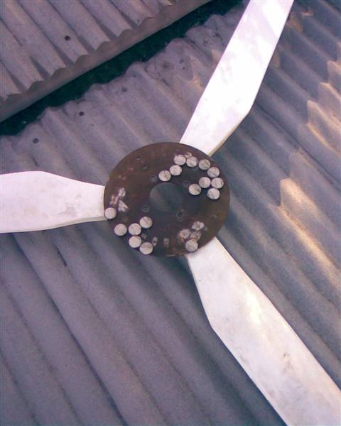
This pic is whats left of the stator a reminder of just how energy 500 watts actually is 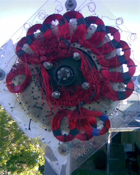
Wind Friend |
||||
| Gill Senior Member Joined: 11/11/2006 Location: AustraliaPosts: 669 |
G'day WF, I guess it's a bit hard to sell now? Seems like it was a prototype and never intended for 25 years of continuous service. Possibly for checking that configuration. I think we can now safely say it's not suited as a full scale production model. As a total rebuild is the only option, your open to all variety of configurations now. Looks like you've lost a magnet or two during the party. Now the real fun starts. Good luck. 
was working fine... til the smoke got out. Cheers Gill _Cairns, FNQ |
||||
oztules Guru Joined: 26/07/2007 Location: AustraliaPosts: 1686 |
Wind Friend, Some things to consider. 1. The magnet spacing between magnets on your disk need to be around a magnet apart. (1/2 magnet minimum) 2. Use a 3:4 coil magnet ratio... 3. use 3 phase not single phase (not 18 mags and 18 series coils... 1ph. 4.Make the coils inner size no less than 3/4 of your magnet diameter. 5.The air-gap (distance from front plate magnet face to rear plate magnet face should not exceed twice the thickness of the magnets, ideally for 3mm mags, that would be a very difficult 4.5mm... which would give s satator thickness of only 2mm....(allowing for mechanical space between mags and stator.. not very practical. Better to have less magnets, and double the thickness. 6. Keep the winding resistance down to an absolute minimum 7. Try for a cut in of at least 8-10 mph, this will help to keep resistance down. 8. Use a blade calculator to find the best size and cutin for your power requirements here: 9. Any magnet wire combination will produce something, but to get the best out of your efforts, these simple rules will go a long way to being more successful. 10 E=IR. For every ohm of resistance, you lose a volt at 1A. for 2.4R, you lose 2.4v per amp... so at 4 amps you lose 10v in the stator x 4amps = 40watts.... so keep resistance low, more mags, less turns, thicker wire , small air gap. The stator you show would be difficult to get decent efficiency out of at any but low power, as the air-gap must have been about 20 or more mm, which would have left little flux for the coils to see... thats why there is a mountain of turns there for only 12v..... which means more resistance and a runaway prop. Do what ever it takes to get the resistance to an absolute minimum.... which will mean that you will have optimised the design anyway... you need more magnet so you can have a reasonable air gap. If you were to stack three on top of each other you could use a 12mm gap, which is do-able. That stator was a disaster waiting to happen, mechanically and electrically I think. .........oztules Village idiot...or... just another hack out of his depth |
||||
| GWatPE Senior Member Joined: 01/09/2006 Location: AustraliaPosts: 2127 |
My calcs gives at best 240W. Maybe 500W of wind energy? Gordon. PS The coils appear to have been cable tied only to an acrylic plate. Each coil as it passes a magnet has a force placed on it that attempts to push the coils. The coils have to be bonded together to prevent any movement. The coils in your photos would have moved enough to cause binding on the magnets. This probably has nothing to do with burning out as such, but a mechanical problem. The wire in the photo above looks thinner than 1.1mm. Are you rewinding with that wire guage? In the first posting you mention 9x2 coils. Now you are talking about 18x1 coils. Good luck with a rebuild. Oztules has made some useful suggestions that will help you. become more energy aware |
||||
| wind friend Newbie Joined: 01/05/2007 Location: AustraliaPosts: 39 |
Hello all Hi Gill quite so it was never intended for 25 years of service, more as a learning thang. Only one magnet came away found on a roof some meters away. Oztules thanks for your advice, the next step is to save up for some more magnets. The whole thing started as something to do and now it has started to take large chunks of time. Thankfully some of the materials were donated. If I stop and do the maths it probably would have been cheeper to do nothing! But nowhere near as much fun. A qustion if I may. As the magnets pass the coils, my understanding is that if the same magnetic field cuts both sides of the coil the voltage is cut to zero rather than falling to zero as the field passes? Gordon the new coils are indeed 1.1mm square - just 6 of thes coils spun up by hand was putting 5 amps into the batteries. I'll have to wind the remainder of the coils and see if 1 x 18 or 2 x 9 is best. The location is a suburban back yard and is marginal at best. May be a second series of windings to drive a relay which can change the windings from series to series/parallel? This would change the resistance to about .6 ohm. It was making 20 amps into 12 volt so yes 240 watt. I'm impressed. Wind Friend |
||||
| oztules Guru Joined: 26/07/2007 Location: AustraliaPosts: 1686 |
from here :talking electronics You can see why point 4 from above does not make complete sense, as the hole should be the width of the magnet. But in the real world, we tend to wind inside the magnet diam a bit to get more turns of lesser wire length... less resistance with smaller diameter really, the induced voltage is less than ideal, but is made up by the shorter circle length. We pull this trick to get more winding space than we would have otherwise, and so can try and get the same number of turns (plus a few extra) with a slightly larger wire diameter..... to get the resistance down. We could of course just keep increasing the height of the coil for more turns, but this increases the air gap... and we lose flux and voltage, and so require yet more turns (like your stator above). It is all compromise, so chose the best compromise you can for the stuff you have to work with. For point 7, the higher cut in you chose, the lower the resistance of your windings, and so closer air gaps are possible, which lowers turns, which decreases air gap etc etc. It appears that for practical purposes (stator strength, winding space etc) that 4.5mm would be the aim for your magnet depth... but not practical, so you will be forced to move away from ideal from the start.... and then it just all gets badder and badder... so to speak ..........oztules Village idiot...or... just another hack out of his depth |
||||
| GWatPE Senior Member Joined: 01/09/2006 Location: AustraliaPosts: 2127 |
I can vouch for difficulties with high flux densities and narrow magnet separations. My axial flux alternator, as has been described on other threads, has 3mm air gap and 2mm coil thickness and 4phases with 0.8ohms per phase, giving an effective resistance of 0.2ohms. When efficiency is of prime importance, then these are the extremes I went to. Gordon. become more energy aware |
||||
| wind friend Newbie Joined: 01/05/2007 Location: AustraliaPosts: 39 |
Hi Gordon, With 18 magnets and 18 coils this would mean 18 peaks or a peak every 20 degrees travelled by the rotor? With 18 magnets and 24 coils would this mean 24 peaks or a peak every 15 degrees travelled by the rotor meaning a greater average output? Or becuse the coils and magnets dont quite line up does this mean the peaks aren't quite as high? A 15 degree arc type coil would cut the centre of one magnet(where the greatest flux density is) and the edge of the next, confusion reigns....... Magnets are 30 mm round and 5mm thick. Current spacing is 16 mm between the faces of the magnets. If I do the poured stator thing I'll be able to reduce this by 4mm, and enter the world of jacking bolts. Wind Friend. |
||||
| wind friend Newbie Joined: 01/05/2007 Location: AustraliaPosts: 39 |
Oops got it wrong Wind Friend |
||||
| GWatPE Senior Member Joined: 01/09/2006 Location: AustraliaPosts: 2127 |
My axial flux rotor with the 3mm air gap requires 11 specially modified 1/4" cap screws with hardened steel opposing posts to push the surfaces apart, on the rotor perimeter. Over 1" of separation is needed before the rotors can be forced apart safely. On the matter of your design, I cannot comment too much. My own design has 44 magnets in total and 44 coils arranged as 4 phases with 11 coils in series and 11 pole pairs on a dual rotor. I have posted a picture of my stator previously. I may get to post pictures of my alternator when I next disassemble it for a bearing lube. How you do it is not too critical. Certain arrangements of phases allows star/delta wiring. My design requires independent rectification of phases. There is a lot of info on other sites like other power etc. It may be worth your while to buy a "how to" boolet from one of the websites. Gordon. become more energy aware |
||||
| wind friend Newbie Joined: 01/05/2007 Location: AustraliaPosts: 39 |
Hi Gordon 20 magnets on each disk, 15 coils each of .11 Ohm, does this make effective resistance of .18 Ohm? new air gap will be 8 mm instead of 17 mm. All these inprovements have got to help. Does halving the Air gap double the flux density? And doubling the output? Wind Friend |
||||
| wind friend Newbie Joined: 01/05/2007 Location: AustraliaPosts: 39 |
New coil lay out works a treat. Cast 3 coils in resin and wired them 3 phase. Lots of current and enough volts. My question is is it better to wind the coils with 1 strand of 1.1 mm square, or 2 strands of .55 mm square copper. Any feed back would be appreciated. Wind Friend |
||||
| GWatPE Senior Member Joined: 01/09/2006 Location: AustraliaPosts: 2127 |
Half the air gap does not double the flux density. Is the air gap still 8mm? Gordon. become more energy aware |
||||
| wind friend Newbie Joined: 01/05/2007 Location: AustraliaPosts: 39 |
Hi Gordon Yep air gap is 8 mm. Now getting enough volts from 250 turns instead of 900 turns! With cutin speed of around 80 RPM. Still dunno about the wire size either 1 x 1.1 mm or 2 x .55 mm. Winding the coils with the finer wire is easier. Wind Friend |
||||
| Page 1 of 2 |
|||||
| The Back Shed's forum code is written, and hosted, in Australia. | © JAQ Software 2026 |
