
|
|
Forum Index : Windmills : Wave Wound Axial Generator
| Page 1 of 2 |
|||||
| Author | Message | ||||
wdyasq Newbie Joined: 29/07/2008 Location: United StatesPosts: 21 |
'Innovative ideas' are usually cheap or free and when it comes time to innovate ... well somebody forgot to tell the designer there had to be an economical way to fabricate the parts. With that in mind, I present a novel approach, or not so novel if one immerses oneself into older publications, on building an axial flux generator. 
The first model is of the stator and magnet plates. This shows a wave wound thin stator. If my numbers are correct, I should get ~50 turns #19 AWG wire I should have twice as many 'cuts' of the flux as a 12 magnet 9 coil machine and a greater flux density. (.0359" diameter wire, slot is .345" X .25" deep and 60% fill was used.) 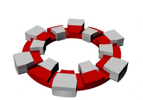
One question is how can it be wound. My second model should explain the top and bottom coil winding I plan on starting off lining the slot with 6mil polyethylene with a couple of straight pieces of fiberglass as used in roving or chopper guns. Then, the copper will be laid in trying to keep the lay somewhat straight When the turns get to proper fill, more glass fiber will be laid in. The coils will then be clamped with the jig shown, the top pulled, a calculated amount of resin and hardener applied and the plastic wrapped over the top and back into the clamping blocks. 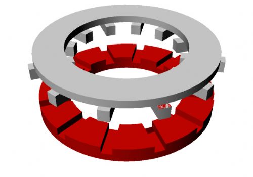
After curing, the coil will be removed. A second coil will be wound in reverse and treated the same. A third coil form will be used for the center coil. The three should mate and fit flat I'm not sure how I will bond all three together. I do have some ideas. I will try to leave turns at the outside and inside as free of resin as possible for heat rejection. I will use a lot of resin saturated glass for strength. Proposed magnets are 1" X 2" X .5". Inner circle is a 4" radius, outer circle is 6" radius. Magnets will have a layer of glass fiber (edit: finer- typo) laid on tops and sides, bonded on before placing the magnets on the rotor plates. There will be minimal epoxy used to bond and pot the magnets. A few turns of stranded glass will circle the magnets as well as a strand or two of Kevlar. Coil length figures 61" a turn or about 304' per coil, 2.45 ohm. Total copper weight about 3.5#. Ron edit noted Adventure is just bad planning." -- Roald Amundsen |
||||
| pepa Newbie Joined: 05/06/2008 Location: United StatesPosts: 1 |
Ron, are there 12 coil legs and 24 magnets, or am counting wrong? thanks, pepa jesse kendrick |
||||
| wdyasq Newbie Joined: 29/07/2008 Location: United StatesPosts: 21 |
You are correct "12 pole". Ron Adventure is just bad planning." -- Roald Amundsen |
||||
| GWatPE Senior Member Joined: 01/09/2006 Location: AustraliaPosts: 2127 |
Hi wdyasq, I suppose my AxFx machine is not wave wound, but has interleaved coils at least. I am intrigued by the amount of wire needed, 3.5 pounds. My completed stator with wire and glass filler only weighs 350g. What expected power output and what output voltage are you hoping for? If you are planning on leaving the inner and outer turns free of resin, I am intrigued as to how this stator can then be mounted. Gordon. PS edit: the arrangement you have is difficult to picture. There appear to be too many magnets, but this may be the 3view. On closer inspection with the top plate reference, this will be OK. Escher would be pleased. become more energy aware |
||||
| Dinges Senior Member Joined: 04/01/2008 Location: AlbaniaPosts: 510 |
Ron, Leaving the blue phase as it is, you will have to rotate the purple phase 10 deg. CCW and the green one 10 deg. CW. Either that, or reverse the start/ending connections of the blue phase, if you want to end up with true 3phase with 120 deg. phase shift between the phases. As you already mentioned, the idea is not new: 
Your wavewound method will yield you the equivalent of 6 normal (round) coils per phase, so 18 coils for the entire generator, whereas the common axial flux has 9 coils total (3 coils per phase) in a 12/9 dual-rotor axial flux generator. If you can build it mechanically, I think you're on to a winner. You will have much more copper (kg) in it than in a normal axial flux, which should translate to lower resistance and thus less I^2*R losses. If you can build it flatter than the normal axial fluxes too, you'll have a stronger magnetic field as well, so can get away with even less turns of copper wire, i.e. less resistance and power loss. I think I would try to wind all the three phases in one go on a mould (with some glasscloth already in it before winding the first phase), then impregnate with epoxy, rather than your plan of winding the three phases individually and then try to mount them together, but we already discussed that. The stator will take more effort, time and care in building (needing more and elaborate moulds), but it should be doable. And yield a superior generator. Aren't there laws against thinking outside the box? Peter. Edit: you may want to look at this patent (5.744.896) too: http://www.google.com/patents?id=iesnAAAAEBAJ&dq=5744896 Not a wavewinding, but still... the method described in this patent using discrete coils looks more easy to execute in practice. 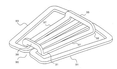
|
||||
oztules Guru Joined: 26/07/2007 Location: AustraliaPosts: 1686 |
Ron, Very nice rendering. Interesting design. What power are you aiming for, at what voltage....It would be helpful if you would provide enough information to form a useful opinion on this design (hehehe insert evil grin here...  ) )
Ok, your stated resistance is incredibly high, and I would hope that you are aiming for a high voltage machine... otherwise I^R losses will kill this off for any useful power . In star it will be 5ohms or so. I don't fancy putting too many amps through that setup. Mine is about .6ohms, for 48v 130rpm cutin and I keep it to less than 20-30A at furling. Without the voltage figures and expected power outputs, we can't determine how effective you will be with the cooling idea...... which brings us to the mounting as Gordon has pointed out..... how is this to be achieved? This article on Fieldlines discusses the pro's and cons of this design. I think that this is effectivly what you are describing.... may have to look closely: 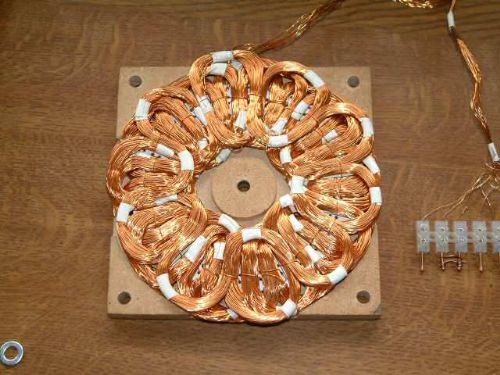
To get useful output you need to aim for sub 1ohm resistances at 48v in either star or delta. I assume you will be going star? If your voltage is 250v or so, then 5R is ok, if at 24v then at 240 watts you will have 10A through your 5ohms in star... so losing E=IR = 50v lost in the winding or 500watts?... in Delta, it will do considerably better r=2.5/2x10=12.5v or 125 watts lost. Need more information.... but looks pretty sad on these figures. ............oztules Ps, Nice to see you posting here Ron, will get the courage up to get onto IRC soon. Edit. I don't know how you arrived at the turns required to get the (whatever voltage). The no of feet of Xawg gives the resistance I know... but if you can see your way clear to get equivalent to say #13 wire into it, it could be useful for a good 1kw for 300' per phase. Not sure how Dinges justified this bit ... if you get more copper into it, it usually means more resistance... unless you go bigger copper. I figure that mass/volt of the same size wire is much better to be less than more. In regards to the "flattening" of the winding space for 3 ph design, this picture from Les Vincent (from Scoraig wind site) shows a radial version of the kind of layout you seem to be trying to achieve in your axial winding 
this does 1kw@320rpm @70% efficiency. or a completed one from Thomas Moore (NZ) 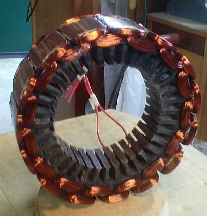
Perhaps Dinges, you should do this with your induction motors  Village idiot...or... just another hack out of his depth |
||||
| GWatPE Senior Member Joined: 01/09/2006 Location: AustraliaPosts: 2127 |
Hi dinges, It seems as though something else I have made has now been patented by someone else, many years afterwards. This goes in the same bucket as SplitPiConverter. I was able to wind my coils in such a way as to keep the phase to phase resistance the same though. Hi oztules, I am a bit puzzled by the resistance as well. I have 187 turns per phase, and my mill produces 30VAC at 400rpm or so, giving 160mV/turn at maximum power loaded. Hi Ron, Your stator has 50 turns for an equivalent 6 coils with twice the wire length in the field to mine, with at least an 8mm magnet spacing. I have 22 magnets per rotor of half the size. I would equate this to your design having a similar amount of magnet, at a wider spacing. My alternator has approx double the output frequency for the same rpm. Your stator is equivalent to 600 turns at half the frequency of my AxFx alternator, with half the magnetic field strength. I will guess here, as I am a bit tired and the numbers have become fuzzy, but I would expect approx 30-50VAC at approx 400rpm. I suspect this alternator will produce approx 500W at approx 75% efficiency. I think the 100-200W stator dissipation at full output may challenge the encapsulating resin. I hope my estimates are wrong. I spent the better part of a year testing coils and magnet spacings and configurations, before settling on the final design, that dinges has pointed out has now been patented by someone else, years after I built mine in 1993-4. Maybe I am just slack, and the financial renumeration aspect is too hard. Good luck with the wave winding. Take care handling the windings once formed. partially encapsulated winding wire is easilt damaged by handling. Gordon. become more energy aware |
||||
| Dinges Senior Member Joined: 04/01/2008 Location: AlbaniaPosts: 510 |
Oztules, Ceteris paribus, more copper (kg) translates into a lower resistance generator. Let's try to think in extremes here: Assume a given generator (magnets, rotors, system voltage, etc). Now imagine two scenarios, where we have two different stators. Both need a certain minimum number of turns if they need to cut in at the required RPM for the given system voltage. But in one stator you're allowed to use 10 gram of copper wire, in the other 10 kg. To get the amount of turns needed in the case of 10 grams of copper wire, you'll need to use very thin wire. In the case of 10 kg copper at your disposal, you can use much thicker wire. Hence, less resistance than in the previous scenario. Generally goes, the more copper (kg) per Watt of generator, the lower the resistance/impedance of the generator. Same goes for magnet fieldstrength (I'm sure you remember that discussion ). Just as we should aim to stuff as much magnet in the generator as (reasonably) possible, I think the same goes for copper.
Ron will be able to fit about double the volume of copper in his generator, compared to a 'normal' axial flux generator of more conventional construction with the same thickness. This should translate into a stator with lower resistance. Of course, as Flux said: he'll have extra resistance in the coil ends that will need to be longer in his generator to clear the magnets and the other coils. Gordon, don't feel too bad about that patent. I was laughing as I read it... how anyone could even receive patent on such a thing amazes me. I bet that with an afternoon of research I could find publications of before 1996 showing people using that idea. I doubt any patent lawyer worthy of that name would have much trouble busting that particular patent. Applying and receiving for a patent is one thing - making money from it is an entirely different issue. I have a very strong opinion on patents, but this is not the time and place. Either way, they're a good source of information and ideas. As far as patents and litigation go... have a look at the lifestory of Edwin Armstrong.... Peter. |
||||
| wdyasq Newbie Joined: 29/07/2008 Location: United StatesPosts: 21 |
You have all given me things to think about .... and after having my ideas and ego bashed and shredded .... I will incorporate what I believe the best of the ideas are and refine. My thought was to get as close to the Otherpower generic design as practical and see the differences. For stator mounting my first thought is to build a hexagonal ring and wrap it with the stranded glass fiber. A very high glass to resin ratio will be held. I could then use short rods of fiberglass to secure the stator to the ring. What I want to avoid is the waste of resin I normally associate with these machines. Some of the reasons I am using particular materials are I have them. I have about 20 pounds of #19 wire and a lot of the 1x2x1/2" magnets. I do plan on doing some tests on a single partial coil and posting results. I am waiting to have some plates cut. Ron Adventure is just bad planning." -- Roald Amundsen |
||||
| oztules Guru Joined: 26/07/2007 Location: AustraliaPosts: 1686 |
Dinges |
||||
| wdyasq Newbie Joined: 29/07/2008 Location: United StatesPosts: 21 |
Being a VAWT, you mean buckets or wings don't you? (NO! I may be ignorant but I'm not CRAZY!) Where some of the numbers came from: I had a slot width of .345" and a depth of .25" giving ~ 0.086 sq.in area. the wide cross section is ~.001" making 'room' for 85 turns 'solid. I think the normal for stuffing cylindrical things on areas is ~60%. I rounded down to 50 turns. The average length of a 'turn' is 12.5" OS and 7.5" inside and 12 x 2-1/2" legs. I came up with ~61" a turn X 50 turns and used that number, 304, divided by 1000 as the multiplier for 8.051 ohm/1000' figure of #19 AWG wire. "2.45 Ohm/coil". Part of this 'experiment' may be a Gorlov mill of the same swept area as the HAWT the stator/magnet assembly shows potential for. Another part of this build will be a friend who claims he can build an MPPT for a wind turbine that will make the alternator suit the source (uh, yeah, sure). I think this will be an interesting year. Ron Adventure is just bad planning." -- Roald Amundsen |
||||
| GWatPE Senior Member Joined: 01/09/2006 Location: AustraliaPosts: 2127 |
Hi Ron, I am bemused. My AxFx alternator has similar magnet volume and probably similar power rating, yet the fully made stator including encapsulant resin and glass fibre weighs in at 350g,[12.5oz]. You calculated the wire alone to be 3.5#, or 56oz, or 1568g in your configuration. This is 4.5 times more copper. I have some internal pics here Gordon's AxFx alternator pics I hope your testing comes back with really high volts/turn to justify this extra copper. Gordon. become more energy aware |
||||
| wdyasq Newbie Joined: 29/07/2008 Location: United StatesPosts: 21 |
Gordon, I see little reason to reinvent products. I am thoroughly impressed by your small genny. I hadn't thought of winding like that but now that I have seen it and I like it. I am guessing you use a square wire. I may have to get or make some of the plate to make a stator similar and test it also. Might need to go 14 - 16" in diameter and actually buy magnets. Ron Adventure is just bad planning." -- Roald Amundsen |
||||
| GWatPE Senior Member Joined: 01/09/2006 Location: AustraliaPosts: 2127 |
Hi Ron, Thanks for the rap. I wish there was a way I could mass produce it. The wire is not square. The wire I had made was 10 in hand, 34#. these are 0.15mm dia enameled wires. [pretty close to coarse hair] I see no benefit with the longer magnets in a small dia axial flux arrangement. You may as well use more smaller magnets at the larger dia. There is an awful lot of air, that serves no useful purpose, in the segmentation gaps between the magnets. twice as many square magnets at the outer radius will give twice the flux transitions at the same rpm. I pushed more magnet in by placing the magnets side by side. I would like to have used segmented magnets, but square was all that was available. I do not wish to put you off, but the simplified way that axial flux mills are made now, with the wider airgap and round magnets and round coils seems to be the way to go. I am tempted to make one this way, but with a closed rotor, with an internally mounted stator. I am not keen on the elements having free reign access to the magnets and stator. Oztules seems to have a good combo and low resistance is a must. Gordon. become more energy aware |
||||
Don B Senior Member Joined: 27/09/2008 Location: AustraliaPosts: 190 |
Hi Ron, I have been contemplating building an axial flux alternator, but my visible progress to date consists of a collection of magnets, a shaft, and some bearings and threaded rod. I had planned to use a 2 phase stator, with each phase coil being 2 wire diameters thick (a spiral in, spiral out configuration). This would put both ends of each coil at the outside, which is where I plan to support the stator. The phase coils would overlap by 90 electrical degrees, and be pressed flat within the active part of the air gap to permit the minimum thickness of air gap. This will, hopefully, give almost continuous copper in the air gap. The inner and outer "end turns" would be sandwiched between thin GRP washers, and the whole lot epoxy encapsulated for rigidity. The intent is for the magnets to protrude from the rotor discs to make more thickness available for the inner end turns. This plan obviously anticipates a lap winding format, but I think that your wave winding scheme might have some constructability benefits. Still thinking about that! One other important point is that I don't understand why designers seem to limit themselves to a single gap axial flux alternator. Perhaps it is a carryover from the thinking for radial flux machines where multiple gaps are much more complicated? It is very simple indeed to have multiple rotor discs, with the end discs incorporating end iron to complete the magnetic circuit. By my measurements, stacking magnets in this way actually increases the flux for a given air gap. By using multiple rotor and stator discs, the alternator output can be increased significantly, without needing to increase the diameter (mind you, a generous diameter is no great disadvantage for a low speed alternator). With the magnets all aligned axially, it is a simple matter to displace the stator discs relative to each other to obtain a multi phase alternator. In my case, I am looking at three stator discs, each displaced by 120 electrical degrees from the others, to give me a 6 phase alternator (with 2 phases per stator disc). This would require, in my case, two rotor discs with end iron, and two intermediate rotor discs, giving 4 stacked magnets per pole. Within the limits of stiffness of the rotor, and other practical considerations, I guess that there can be a large number of discs stacked up, and you can suit yourself how the stator discs are displaced, and hence how many phases you choose to have. I take Gordon's point about supporting stators internally to minimise the intrusion of the elements, but I don't think that this is an insuperable problem for external support, and it certainly makes for simpler assembly where multiple discs are employed. Food for thought? Regards Don B |
||||
| GWatPE Senior Member Joined: 01/09/2006 Location: AustraliaPosts: 2127 |
Hi Don, I had wondered how to describe the way I wound the coils on my AxFx alternator. The spiral in spiral out does nicely. I started at the inside turn, and wound both ends out, simultanously and in opposite directions. This is what I used the mould for, that I gave a pic of here. I had considered stacking of multiple units as well. The problem that is encountered is assembly. Supporting the rotor and aligning of the stators between sections will pose some engineering problems. In my design, the axle could be through bolted. The rotor could also be through bolted around the perimeter. The inner bearings would need to be removed. The rotor would only need to be supported on the outermost bearings. I would imagine you could throw a lot of crinkly at the problems and get a solution though. There are real engineering problems with designs that incorporate large amounts of permanent magnetic material. I guess this is why usual power station alternators use iron and electro magnets. Multiple stators could make a more compact alternator, but I could not justify the complexity when I built my AxFx unit. I don't think too much has changed since then. Gordon. become more energy aware |
||||
| Dinges Senior Member Joined: 04/01/2008 Location: AlbaniaPosts: 510 |
Oztules, I've actually considered doing something like this. About a year ago I checked the motors whether they had a perfectly round outer stator (no flats/slots/etc.). Only one of the 6 or so I checked was perfectly round. I'm saving that stator for exactly this purpose. Recently I stumbled upon this rotor from an old ceiling fan: 
After removing the aluminium casting bits that were in the way, I ended up with a perfectly round laminated iron core, 10mm wide, 153mm outside diameter. This should make a nice little (100W?) non-cogging iron cored radial flux generator. Likely will never happen though, as it'd only be a plaything. I'm not going to invest my time and effort building small generators, when nearly the same effort would result in an actually usable large generator. But maybe someone else has some use for this idea. Peter. |
||||
| oztules Guru Joined: 26/07/2007 Location: AustraliaPosts: 1686 |
Don B, Multiple stator stacking has been done before by a few people on fieldlines. The only thing it seems to be better at is making for a smaller diameter unit. Other than that, it's all negative. (poor use of available magnets, and copper). Unless there is a pressing need for a smaller diameter unit, better use of resources will be a single larger unit with the same magnet volume..... interesting discussion here ...........oztules Village idiot...or... just another hack out of his depth |
||||
| Don B Senior Member Joined: 27/09/2008 Location: AustraliaPosts: 190 |
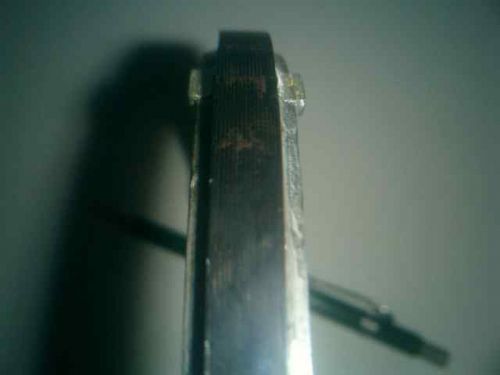
Hi Oztules, Thanks for the response, and the link to the Otherpower.com forum. Actually, the photo of the multi rotor machine sent in by Powerbuoy on 26-03-06 is very similar to the mechanical construction that I had in mind. While I take the point that large diameter single airgap machine may make more economical use of materials (and perhaps be more efficient?) than a multi-rotor machine, there are some points that should be considered before we all walk away from the multi rotor concept. The first point relates to the number of phases that you can readily fit into a single stator. Generally, the more phase coils that you have, the wider the air gap that you will need to accommodate them, and I imagine that the 4 phases that Gordon has used would be about the practical limit. A wider air gap means a less efficient use of your magnets. The old bugbear of audible cogging (or clogging, if you are in to tap dancing) under load will diminish as the number of phases increases, and many phases are possible with a multi-stator machine. As a flight of fancy, a two phase 90 degree displaced wave wound stator could be produced using something similar to a double sided printed circuit board. The problem is that the copper in PC boards is in the wrong plane (bad for eddy current losses), and is ordinarily way too thin anyhow. If you could somehow get thick copper each side and photo or laser etch the winding so that an adequate area of copper could be obtained with the thickness in the axial plane, you might have the basis for a mass produced multi stator alternator. Not really a back shed project though. At a lower flight level, it may be possible to use wave or even double spiral lap winding with copper (or aluminium) ribbon, interleaved with insulating material a la capacitors? That would at least put the conductor width in the appropriate axial plane. Or you could do the smart thing, and use a kind of Litz wire, as Gordon did. On the Otherpower site there was some concern expressed as to the effect on flux density of having more than one air gap per pole. Some seemed to think that having two gaps would result in only half the flux density in each, or somesuch. While I would not have expected this with multiple magnets, flux density was also of concern to me, as, should the flux vary significantly across the air gaps in a stack, then the voltages produced by the stator coils would vary, and cause problems. I have made up a rough rig and taken some flux measurements of different air gap arrangements with magnets that I have on hand From my tests, it seems that, as long as you have the same length of magnet per air gap, the flux in a closed circuit stack of magnets and gaps remains pretty uniform (length does seem to matter, in this case). My tests were performed with two stacks of NIB magnets that are 21mm diam, and 5mm thick. The test stack was separated from the return stack by a magnet diameter, and 2.5mm thick steel end plates were used to close the magnetic circuit. For a single 3.6mm gap in both stacks with 1 magnet either side of the gap, I measured a maximum gap flux of about 8,600 Gauss (or 0.86 Tesla, if you prefer). With a 3 gap stack, again comprising 2 stacks with end plates as above with each magnet stack set up as 1 magnet, 3.6mm gap, 2 magnets, gap, 2 magnets, gap, 1 magnet (ie equal magnet length per gap), I measured a maximum flux in each gap of about 8,700 Gauss. The attached photo may clarify my description somewhat. As an aside, the maximum flux measured on the face of a single magnet in air was 2,900 Gauss, so the importance of having a complete magnetic circuit to concentrate the flux is evident. With NIB magnets, I gather that 10,000 Gauss (or 1 Tesla) is about the maximum flux density that you could obtain in the best of circumstances, so I think that 8,700 Gauss in a 3.6 mm wide gap is a very useable figure. It was also interesting to note that the maximum leakage flux measured on the other side of the 2.5 mm thick steel end plate was only about 100 Gauss, so the plates don�t need to be very thick to satisfactorily complete the magnetic circuit. The actual end rotor disc back iron would probably need to be 5 or 6mm thick to resist significant bending due to the magnetic attraction of the pole magnet stacks, but the intermediate discs would be more or less in balance from the attraction of the gaps on either side and would not need to be so stiff (once properly centred). While thinner steel could also be used for the intermediate disc spiders, it is clearly not necessary to close the magnetic circuit at each rotor, and may even result in greater variability of the air gap fluxes. I have not tested for this circumstance. I do wonder about the possibility of eddy current losses in a steel intermediate rotor disc from the alternating fields set up by the stator coils. Anything conductive, such as aluminium or carbon fibre, might well have the same problem. Maybe fibre glass would be best for the intermediate rotor spiders, as the centrifugal forces in a low speed alternator at least are not huge. Incidentally, I have an excellent book published by Springer, called Axial Flux Permanent Magnet Brushless Machines. While I don�t pretend to have absorbed more than a tiny fraction of its contents, it is certainly the most comprehensive book on the topic that I have come across. Regards Don B |
||||
| GWatPE Senior Member Joined: 01/09/2006 Location: AustraliaPosts: 2127 |
Hi Don, The coils in my design are in the same plane. There are not multiple layers for the phases. All the phases are effectively side, by side. The air gap is not changed by the number of phases. The airgap is still 3mm, with a 2mm coils thickness. On another point: The main concern I would have for multiple stators in the configuration you are suggesting is how to mount the magnets that are in the centre sections. If these magnets are half the thickness and share a common iron support plate, this may work. The number of phases; I don't see a real problem with the way I made mine, to make 5, or 6, or 7 phases. More phases just mean more rectifiers and in my case, less turns per phase. I was able to get 748 total turns. I chose 4 phases as I needed a certain emf at a certain rpm and only one wire size. This dictated 4phases in the available air gap. For 5phases, this would allow 150 turns per phase. There would be a reduction in output emf for the same rpm of 150/187. For 6phases, this would allow 125 turns per phase. There would be a reduction in output emf for the same rpm of 125/187. For 7phases, this would allow 112 turns per phase. There would be a reduction in output emf for the same rpm of 112/187. etc etc. If I was to make a 7phase unit, this would translate to an operating rpm of 187/112 to produce the same emf and current per phase. The output power would be increased by 7/4. This would be the same result as say a rewire for for a F&P. Gordon. become more energy aware |
||||
| Page 1 of 2 |
|||||
| The Back Shed's forum code is written, and hosted, in Australia. | © JAQ Software 2026 |
