
|
|
Forum Index : Windmills : trying to build 1st windmill
| Page 1 of 2 |
|||||
| Author | Message | ||||
divemaster1963 Regular Member Joined: 28/01/2009 Location: United StatesPosts: 46 |
I have loads of questions. does any;one have sugestion? I build my first one. just charging 6 12volt marine batteries I got from a gem car I working on. 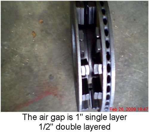
|
||||
CraziestOzzy Senior Member Joined: 11/07/2008 Location: AustraliaPosts: 152 |
G'day mate, just a quick question, you have two rotor discs with magnets affixed to each in the first photo...where are your coils going? It seems from the last photo, that you are using magnets as the core for each of your winding sets? Cheers http://cr4.globalspec.com/member?u=25757 http://www.instructables.com/member/OzzyRoo/ |
||||
| divemaster1963 Regular Member Joined: 28/01/2009 Location: United StatesPosts: 46 |
howde partner from georgia, usa. the stator will be laminated in epoxy and will be stationary between the two auto disc brake rotors. the air gap will be adjustable with shims between the hubs. I'm trying for 1/16 th air gap. the bearings on the hub are the size of big marbles. 1/2 inch dia. |
||||
| CraziestOzzy Senior Member Joined: 11/07/2008 Location: AustraliaPosts: 152 |
I figured that may be case with a stationary disc in the middle. I think using what you have, will work...albeit not ideal but great for a DIY job using what you got 
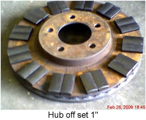
I would personally try and get another rotor disc shown on the left of your first photo...better for the magnetic flux to complete a circuit rather than have loss and more eddy currents occur relative to the air cooled one to the right. Your air gap is dependent on what your end product will mechanically allow and also the amount of cogging you may experience. You mention an offset of 1 inch...so cogging is not an issue but phase timing will be. I think you should determine alignment of opposing magnets on each of your two disks once you have the unit assembled and have them close to opposite as possible....just my thoughts http://cr4.globalspec.com/member?u=25757 http://www.instructables.com/member/OzzyRoo/ |
||||
| divemaster1963 Regular Member Joined: 28/01/2009 Location: United StatesPosts: 46 |
they are the same disc. I just cutoff the back side then turned it true smooth with a brake machine. man cuting that thing gave a new meaning to hard days work. it took about 3 hours. with a sawzall and metal blade then grinding then milling.  but I guess I have to workout first. hay sofar I have 18 us dollars in it. but I guess I have to workout first. hay sofar I have 18 us dollars in it.  including 12 batteries, copper mag wire 14 size. 50 foot tall 12 inch at base 4inch at top.. spun aln. light pole. 100 feet 4 guage 3 strand all weather wire. pvc watermain pipe 10 feet long 8in dia. 1/2in thick.1/4 steel plate to make mount for hub including 12 batteries, copper mag wire 14 size. 50 foot tall 12 inch at base 4inch at top.. spun aln. light pole. 100 feet 4 guage 3 strand all weather wire. pvc watermain pipe 10 feet long 8in dia. 1/2in thick.1/4 steel plate to make mount for hub |
||||
| CraziestOzzy Senior Member Joined: 11/07/2008 Location: AustraliaPosts: 152 |
Crikies, now you have to do the other disk 
For all the weekend coffee drinkers, might be great to see some pics of what you got lined up to put together? Also might be of benefit to you, in case you overlooked something obvious, I know I did today, but that's another story 
Your magnets are curved on their face? If so, have you determined polarity for N-S? http://cr4.globalspec.com/member?u=25757 http://www.instructables.com/member/OzzyRoo/ |
||||
| divemaster1963 Regular Member Joined: 28/01/2009 Location: United StatesPosts: 46 |
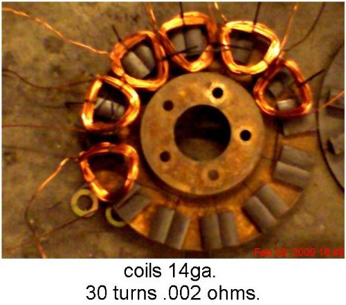
the next step is the form for the stator. scrape wood from the remodeling next door to me. if the rain would stop.  do you think the windings are good enough. it all the man had at the time. I just got done unwinding a gas generator. found 8 lbs. of no. 17 ga. wire in it. hey 2 17's in hand equal 14 at the same no of turns. do you think the windings are good enough. it all the man had at the time. I just got done unwinding a gas generator. found 8 lbs. of no. 17 ga. wire in it. hey 2 17's in hand equal 14 at the same no of turns. |
||||
| CraziestOzzy Senior Member Joined: 11/07/2008 Location: AustraliaPosts: 152 |
OK, a couple of questions to answer yours, How thick is the disk you machined on your first photo? What type of magnets are you using (what are they taken from may help) and what are their dimensions? Any chance you could confirm your magnets are curved on their face? If so, have you determined polarity for N-S? And finally, a quick diagram or sketch to show the proposed arrangement for your magnets on both disks, including polarity...I am a bit confused about your arrangement of magnets as each photo seems to be different. http://cr4.globalspec.com/member?u=25757 http://www.instructables.com/member/OzzyRoo/ |
||||
| divemaster1963 Regular Member Joined: 28/01/2009 Location: United StatesPosts: 46 |
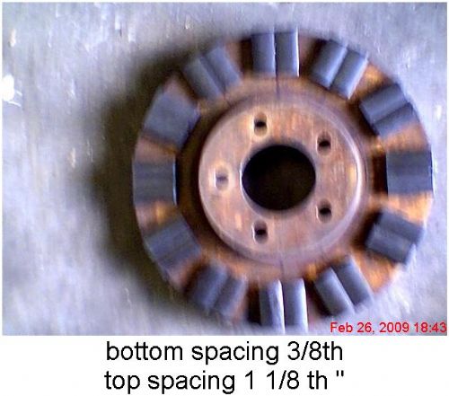
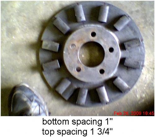
the disk machined out to 3/16 thick no bleed thru from mags. the mags are ceramic from ford starter motors. 2 inch long 1 inch wide 1/2 inch thick. slight curve on face. 1/32 off flat in center.faces are single polarity . I have not figured out which way to arrange mags yet double up or in pairs of 2nn and 2ss. for total of 12 on each rotor. |
||||
| divemaster1963 Regular Member Joined: 28/01/2009 Location: United StatesPosts: 46 |
which way would you sugest I arrange them to get the best output. I am think 3phase star with bridge retifiers. |
||||
| GWatPE Senior Member Joined: 01/09/2006 Location: AustraliaPosts: 2127 |
For the 12 pole magnet arrangement, you will need 9 coils arranged as 3phase with 3coils per phase. I doubt that 30 turns per coil will be enough. You will need to confirm sufficient emf for the design rpm, and loading and rotor area. Do you have some idea of how big this mill will be? Gordon. become more energy aware |
||||
Bryan1 Guru Joined: 22/02/2006 Location: AustraliaPosts: 2102 |
Hi Divemaster, Just how strong are those ceramic mags ? If your going to want some decent power get rid of them and get some neo magnets. Over there in the US neo's are cheap. As your using 2x1x1/2 check these mags out. I'd hate to see you go thru all that work and find you have only a 100 watt genny at best. Also checkout otherpower and see how they did the disk brake gennies as that will give you all the pointers you need. Cheers Bryan |
||||
| CraziestOzzy Senior Member Joined: 11/07/2008 Location: AustraliaPosts: 152 |
Unless someone beats me to it, I will run a quick simul on FEMM using your measurements, magnet specs and also take into account the metal composition of your brake rotor discs. Check this post in the morning Your curvature on the pole faces may be a challenge for you later as far as getting air gaps right are concerned...might need a bit of machining to flatten crests which means doubling up the mags is a good idea. The suggestion of NEO'S is a great idea if you wish to spend a little money to compensate for your efforts. Check this LINK out for coffee cup reading... http://cr4.globalspec.com/member?u=25757 http://www.instructables.com/member/OzzyRoo/ |
||||
vawtman Senior Member Joined: 14/09/2006 Location: United StatesPosts: 146 |
Those mags would be nice dual rotor radial candidates.Let me know if you decide to sell them and get neos.How many have you got or can get? |
||||
| GWatPE Senior Member Joined: 01/09/2006 Location: AustraliaPosts: 2127 |
Hi vawtman, it was stated that the mags were ferrite type from Ford starter motors. These would be designed for about a 3" rotor dia. I suspect the VAWT alternator rotor would be much bigger, so magnet grinding would still be on the cards. Gordon. become more energy aware |
||||
| vawtman Senior Member Joined: 14/09/2006 Location: United StatesPosts: 146 |
Hi Gordon My thoughts were more geared to toy turbines.I wonder how the f@p would benefit from a dual rotor in place of the pregnant stator it has now
I used arced neos on a 5hp conversion and the whole thing seemed mushy(iron saturation)These may cut back on the mushies and still be almost has productive overall  Don't know Don't know
I can't think of anyone that converted Zub motor using ceramics. One could easily fit 12pl on 6in pulley for dual |
||||
| CraziestOzzy Senior Member Joined: 11/07/2008 Location: AustraliaPosts: 152 |
I did a FEMM test on the OP's arrangement and decided was worth while not putting the results up and agree with GWatPE :) You will have to have more turns of that wire you have available to get something decent without spinning your proposed genny at the speed of light. You will need to settle for a smaller gauge wire using the current setup you have shown. You also need to do some grinding work on those magnets you have as mentioned earlier too and make sure you are aware what is really involved with the circuit of magnetic flux. Your current arrangement produced a crazy amount of loss in the two backing plates holding your magnets and the amount of eddy current induced was ugly. Keeping in mind you are using what you have available, I would suggest you figure out a suitable core/coil arrangement and number of poles (as mentioned by GWatPE), so that the magnetic flux does not bypass the centre winding of your coils. I can't add much more at the moment...have to play house bitch for awhile. Cheers http://cr4.globalspec.com/member?u=25757 http://www.instructables.com/member/OzzyRoo/ |
||||
| divemaster1963 Regular Member Joined: 28/01/2009 Location: United StatesPosts: 46 |
thanks I found some 17 gauge wire for to old gas gen's that engine died on . I removed the wire. it 17 size. I have about 6 lbs. I may try and make some new coils. I think I can get 6o turns two in hand. I post picks when I get them made. what no. of turns do u suggest. I have more wire. possible 21,23,24 gauge. any suggestions.The magnets have a raised area of about 1/32 in in center> I was hopeing that auch a small high spot would not effect the field as much. these magnets can be found at any alternator/starter shop. they throw them away and don't rebuild them. I have unlimited supply. I would love to find a f&p motor here in ga. usa. but they are like finding a tasmaining devil in my back yard here ing the south . I have called every whrere. and I have a scrape yard owner Keeping a eye out for them. I also have some collectoin center in the counties keeping a eye out. |
||||
| vawtman Senior Member Joined: 14/09/2006 Location: United StatesPosts: 146 |
Hi Dive I would shy away from the 2 inhand 17 idea.Maybe 300 turns of #24 with iron filings or powder has a core for the coils.Those mags need all the help they can get.Then just go the standard 12/9. I still think they would work better for a motor conversion.The steel is right there then.No gap to jump.One could even give em a slight skew with grinding wheel since heats not a factor unlike the neo. Have fun and keep Diving |
||||
oztules Guru Joined: 26/07/2007 Location: AustraliaPosts: 1686 |
Divemaster, If you wish to make an axial from ceramics, then I think a read of Jerry's antics with them on Fieldlines (otherpower) forum will give you some hope of decent output with ceramics and axials. His first story on the 14/11 is interesting. If you go to Jerry's diary, you will see a list of entries (about 5 I think) for the start to finish of a very nice useful little 300w machine, with ceramics. Jerry uses true Jerry-rig for the coil outputs, where every coil has it's own rectifiers, and every coil carries the total terminal volts independant of any other coil. So it is really 11 single phase machines in 1. This has the advantage that when he needed to increase the flux between plates, he chose a magnet:coils ratio that would negate cogging when he then filled the coil centers with metal to focus the flux. Because he didn't need to use a three phase magnet to coil ratio, he could go 14/11 (to naturally neutralize the iron cogging) instead of 12/9 etc....Cunning and interesting project, and worth a read if your going the ceramic route. .............oztules Village idiot...or... just another hack out of his depth |
||||
| Page 1 of 2 |
|||||
| The Back Shed's forum code is written, and hosted, in Australia. | © JAQ Software 2026 |
