
|
|
Forum Index : Windmills : Homegrown - Ax Fx -
| Page 1 of 2 |
|||||
| Author | Message | ||||
fillm Guru Joined: 10/02/2007 Location: AustraliaPosts: 730 |
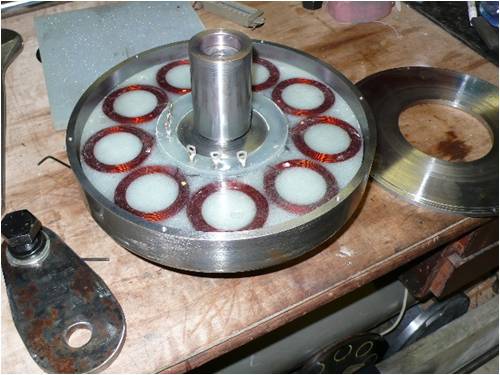
Hi All, Well I have been inspired buy all the talk to get in and build an axial flux generator to the same design specs that Gordon is working on as well , as it is my first and don't know a lot about the tech side of these I am taking on board the advice I get and put the folding stuff into , and hopefully launch onto a new learning curve .. Anyway I shot of some Pics 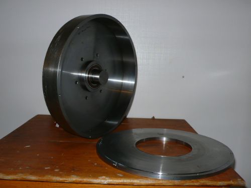
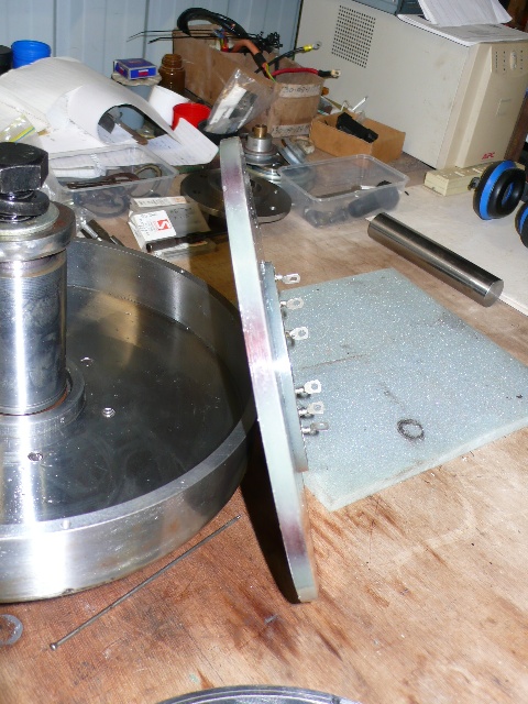
The Rotor Housing with the back of , this was a whole lot of fun in my lathe as it is getting towards the max size I can swing over the gap bed 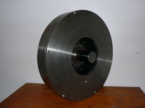
Housing with the back on 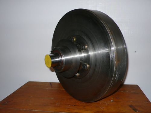
Front showing the bearing hub and flange for my blade hub , the bearing will sit back and a cover plate will bolt on so the bearing seals can be removed ( except the back bearing seal ) and they will run in light oil.. 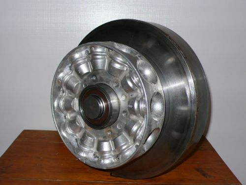
The blade hub , soon to be tested out for strength when I shut it down it should come to a screaming sudden stop an any blow .. 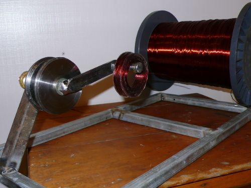
The coil winder , I wound the first coil today , it ot a bit messy towards the end , the 100 turns still ended up with an OD of 72.5mm .. 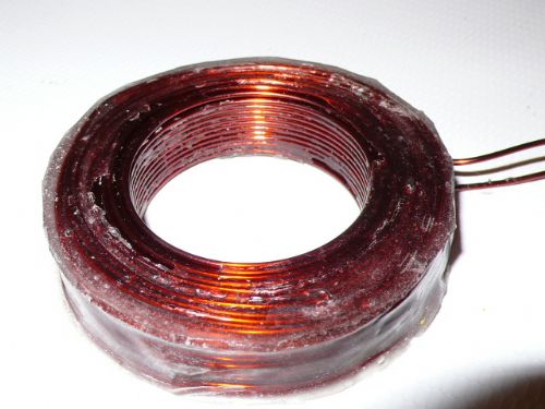
The first coil , against the best advice I used 5 min epoxy , and it was a bit messy and to quick , the next one will be with the proper epoxy , some poeple just don't listen ... PhillM ...Oz Wind Engineering..Wind Turbine Kits 500W - 5000W ~ F&P Dual Kits ~ GOE222Blades- Voltage Control Parts ------- Tower kits |
||||
| GWatPE Senior Member Joined: 01/09/2006 Location: AustraliaPosts: 2127 |
Hi Phill, looking good so far. I will have to send an express bag with some wire in it. The coils look pretty good as well. On my unit, the flange that holds the stator is also bolted to the yaw box. Make sure there is enough room to fit the stator central in the magnet gap, without interfering with the bearing housing. I guess you can see if things will fit. At this rate you will get to fly your mill pretty soon. Gordon. become more energy aware |
||||
| sPuDd Senior Member Joined: 10/07/2007 Location: AustraliaPosts: 251 |
That�s some sexy machining there Phill. Did you weld the front plate to some huge diameter slice of metal pipe? How will this unit go for cooling if sealed Vs the conventional open frame design? sPuDd.. It should work ...in theory |
||||
oztules Guru Joined: 26/07/2007 Location: AustraliaPosts: 1686 |
Dont forget to put in a system to get it apart 
I am a little worried about the cooling, ( the wire looks about 1.2mm... pretty fine for 100 turns with no air cooling......perhaps powder coat it a matt black to try and keep the air inside as cool as you can. It looks spectacular though. If the cooling holds it will be an absolute pearler. Mine has 100t of 1.8mm, and gets warm at 800-1000w... but is air cooled. Driving a grid tie, it should be ok, driving batteries, I would be worried. Great effort though (makes mine look less than agricultural) ..........oztules Village idiot...or... just another hack out of his depth |
||||
imsmooth Senior Member Joined: 07/02/2008 Location: United StatesPosts: 214 |
Oztules, How are you cooling your stator? Have any pictures? |
||||
| GWatPE Senior Member Joined: 01/09/2006 Location: AustraliaPosts: 2127 |
The design is not fully sealed, but is actually open on one side. There will be enough windage from the magnets, and the casting of the stator, to give adequate cooling. It is intended that there will be several holes in the ring. These will be for drainage of water that may enter the rotor. The holes will also provide the action of a centrifugal fan to move air across the stator. The stator resin encapsulant will ultimately determine the temperature that can be withstood. The combination of furling and conservative rotor dimensions will ensure the stator is not overstressed. On my mill, I am looking at a current and voltage sensing arrangement that will allow for rotor braking if either exceed a preset value. The power levels that are achieved and the the temperature that may be attained will depend on the level of sustained wind. My AxFx mill has produced 25A with tiny wire without burning up. I was a little hesitant with the 1.25mm wire. In my original AxFx unit, I measured considerable drag when thick wires were used and the unit was spun unloaded. Eddy currents in large dia wires have not been ruled out in this design yet. Large dia wires do simplify the windings though. The physical size of a machine over 12" in dia does push mechanical limitations of machine tools available to make an assembly. If the machine has to be furl limited to 900W, then this will probably not matter much. The average wind conditions expected will determine the settings for rotor blade sizing and furling and hence the average power. The stator will not suddenly overheat. Phill is in a similar position to me with location of his mill, close to house, in a built up area. An efficient mill that works in all winds, that is quiet, and is not a liability in stronger winds is a prime objective. Gordon. become more energy aware |
||||
| fillm Guru Joined: 10/02/2007 Location: AustraliaPosts: 730 |
There seems to be great concern over cooling the stator , as Gordon has explained some of the details with having a open back plate and holes in the housing ring . Other ideas I am toying with is an aluminum fan that fits into the gap between the shaft and back rotor plate hole and draws more air through the outer holes , also moulding the stator onto an aluminum mount plate that has concentric grooves machined into it to increase the surface area and draw heat from the stator...Phill PhillM ...Oz Wind Engineering..Wind Turbine Kits 500W - 5000W ~ F&P Dual Kits ~ GOE222Blades- Voltage Control Parts ------- Tower kits |
||||
| oztules Guru Joined: 26/07/2007 Location: AustraliaPosts: 1686 |
Gordon, ". My AxFx mill has produced 25A with tiny wire without burning up."..... My understanding is that your current AxFx, is all suface area, and no core, so thermal exposure is massive compared to core temp of a compact core..... If you can change the air regularly, or use the shell to keep the internal air cool.... you stand a good chance. Bench testing should give you a fair idea, as convection cooling from incident wind will play less of a role than with open construction. ..........oztules Edit, I just saw Phils comment. Please, no metal in the changing magnetic field... except for the coils..... eddy currents will be horrendous if I'm reading your Al comments right. Village idiot...or... just another hack out of his depth |
||||
| GWatPE Senior Member Joined: 01/09/2006 Location: AustraliaPosts: 2127 |
Hi Phill, as oztules has said, NO metal , especially aluminium, or coppper in any location that feels the alternating permanent magnet flux. You had planned on some lathe run testing, so this will pick up potential problems. Gordon. become more energy aware |
||||
Bolty Regular Member Joined: 03/04/2008 Location: AustraliaPosts: 81 |
Hi Phill I very much like the iron around the outside allowing a return magnetic path for the magnets opposite each other. In my opinion, this should strengthen the axial magnetic flux. Very good looking work! Bolty |
||||
| fillm Guru Joined: 10/02/2007 Location: AustraliaPosts: 730 |
Oz,Gordon , I am not sure I explained about the Al flange idea , it would have an OD approx 120mm and allow the stator to bolt securily to a steel flange welded on to the shaft , the id of the coils inner edge would still be 20mm or so away from the Al flange edge and but bound together by epoxy . Would this still create eddy currents ? Just trying to strengthen to mounting of the stator and make it easy to hold in the lathe for final sizeing , if not Al what about steel ? PhillM ...Oz Wind Engineering..Wind Turbine Kits 500W - 5000W ~ F&P Dual Kits ~ GOE222Blades- Voltage Control Parts ------- Tower kits |
||||
| Bolty Regular Member Joined: 03/04/2008 Location: AustraliaPosts: 81 |
I was also thinking about all the concerns about cooling. I will go through some thinking to hopefully reach a logical end point! I do not know how much space you have between each magnet (not the airgap across to the other face, but the distance between each magnet on the same face�I will call the magnet on the same face the adjoining magnet, whilst the one opposite across the axial airgap, I will call the opposite magnet). I have a hunch that a lot of the magnetic field lines flow between adjoining magnets. Due to the effect of the opposite magnet, some field lines will cross the axial air gap. However if the adjoining magnet on the same face is closer, most of the field lines will flow to the adjoining magnet, and not cross the axial path to the opposite magnet. These field lines between adjoining magnets would not cut the coil, and therefore would not contribute to any generation. This effect would be due to the reluctance of the magnetic path to the adjoining magnet being much less than the reluctance to the opposite magnet. For a description of reluctance look at http://en.wikipedia.org/wiki/Reluctance Hence the magnetic path will be in the path of least reluctance. This reduction of axial flux will be further exacerbated by the opposing flux from the stator coil, which will tend to repel the axial field lines even more, forcing them to the adjoining magnet. This is all my opinion based on Gordon's design. We have discussed this concept together, and Gordon is of the opinion that the reduction of axial flux is not an issue. I have raised the opinion that if there were slots cut in the faces between each of the adjoining magnets, that this would introduce an air gap between adjoining magnets. Rather than having the iron disk to flow through, the dramatically reduced permeability of air compared to steel (around 780X), would result in the field lines flowing around through the iron, across the outer surface, and back to the other side disc. This should therefore redirect the available flux lines from going to the adjoining magnet, and instead completing the magnetic circuit by travelling across the axial air gap. That is, assuming that the reluctance of this longer magnetic circuit is less! It all comes down to the size of the air gaps in each of the possible magnetic circuits. That is, the air gap between adjoining magnets needs to be greater than the axial air gap. It seems logical to me that a design which maximizes the magnetic flux from each of the magnets into the axial air gap, will maximize the output of the alternator. Where this all ends for your design, is that you have an option that would possibly allow you to both increase the axial magnetic flux, and provide a cooling path for your stator. I have attached a rough paint sketch that should give the idea. I have only drawn one airgap (white). I have not seriously thought too much about the shape of the airgap that would optimize the axial flux, as it is effected by the geometry and dimensions of your rotor and magnets. It is my opinion that a shape which increases the reluctance between adjoining magnets, must increase the axial magnetic flux. Hopefully the gap would also allow cooling air to flow through! I do not proclaim to be an authority on any of this. This is just my interpretation of how changing the reluctance of the possible magnetic paths can possibly increase the axial flux! 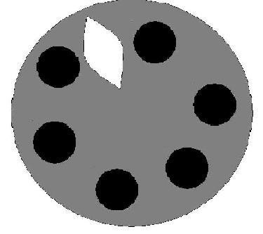
|
||||
| oztules Guru Joined: 26/07/2007 Location: AustraliaPosts: 1686 |
Have a read of this Bolty, it may calm your reservations. Provided the intermagnet gap is at least the air-gap, there is no real problem with it... In this case I think it is about 5/8th inch. We don't want slots/gaps between the magnets, this defeats the purpose of the plates... we must join the flux up... like an electric circuit... exactly the same thing. If you look at Sir Dinges animations, this will become clear. The high flux densities are indeed between the magnets through the plate... thats why we put it there.... this leaves wanton free lines on the magnet face with no-where to go... except through the airgap to the other side... or to the magnet next to it... through the air. So providing we have an airgap less than the intermagnet gap, we will win. The armature reactance has not been shown to be relevant with the axial flux's, because if you graph it's power curve it is basically a straight line Here is mine on it's first test into batteries. 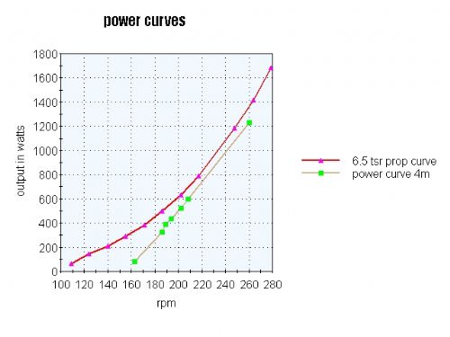
...........oztules Village idiot...or... just another hack out of his depth |
||||
| GWatPE Senior Member Joined: 01/09/2006 Location: AustraliaPosts: 2127 |
Hi oztules, There is one aspect of this design, that I will now be checking. I will remove 1/3 of the magnets from my test rig and redo the 1 turn testing. I suspect there will be a tradeoff between an increase in coil emf due to lower flux leakage between magnets and a decrease in emf due to the lower flux transition rate. As long as the flux leakage is less than 1/3 of the total flux then the extra magnets will still win out. I have tried to place as much magnet into this small plate area, at the largest radius to still fit within the 12" pipe. Will confirm soon. Gordon. become more energy aware |
||||
| oztules Guru Joined: 26/07/2007 Location: AustraliaPosts: 1686 |
More magnets.... more power 
It would need to be pretty asymmetric to get otherwise I think. .........oztules Village idiot...or... just another hack out of his depth |
||||
| fillm Guru Joined: 10/02/2007 Location: AustraliaPosts: 730 |
Bolty , wether slots can improve the flux lines or not I dont know , but I do know that to put them in would be a trying exersize in machining unless you had some pretty fancy machinery or a whole lot of time , but thats not to say it can't be done . Just knocked the second attempt of coil winding out of the mandrel , heaps better than the first , used the right epoxy this time which gave more time to be a little neater , OD now 66mm from 70mm on the first.. 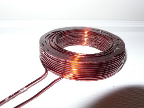
PhillM ...Oz Wind Engineering..Wind Turbine Kits 500W - 5000W ~ F&P Dual Kits ~ GOE222Blades- Voltage Control Parts ------- Tower kits |
||||
| imsmooth Senior Member Joined: 07/02/2008 Location: United StatesPosts: 214 |
That looks really nice. Isn't epoxy more sensitive to heat than fiberglass resin? Or, is this temporary until you set the coils? |
||||
| GWatPE Senior Member Joined: 01/09/2006 Location: AustraliaPosts: 2127 |
I have just completed the coil test and there is only a 1mV difference in output emf at 150rpm, from 107mV to 108mV. The reduction in magnets from 12 to 8 would require 1 less coil per phase as well. The increase in turns per coil to get the required system voltage would not be complimented by the thicker wire that could be placed in the gap, so it seems that there is little leakage flux between magnets. If the flux leakage was significant, then the single turn coil emf would have increased at the same rpm, and it did not. Gordon. become more energy aware |
||||
| fillm Guru Joined: 10/02/2007 Location: AustraliaPosts: 730 |
Heres the finnished stator 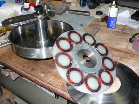
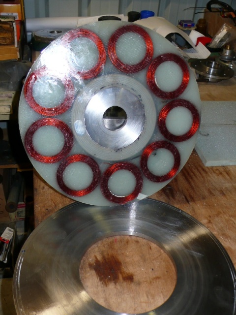
And now the fun part comes with putting the neo magnets into place and lowering the plates together with a tool I will screw into the 1" UNC in the shaft .. I'm not sure of how much force these magnets will have when there is 24 trying to pull each other together 13mm apart, but my finger knows how much 1 can exert  . .PhillM ...Oz Wind Engineering..Wind Turbine Kits 500W - 5000W ~ F&P Dual Kits ~ GOE222Blades- Voltage Control Parts ------- Tower kits |
||||
niall1 Senior Member Joined: 20/11/2008 Location: IrelandPosts: 331 |
big kudos to phill and gordon great to see a design out there on the edge ...... ........ ...... .... but honey i really do need to buy a lath.... niall |
||||
| Page 1 of 2 |
|||||
| The Back Shed's forum code is written, and hosted, in Australia. | © JAQ Software 2026 |
