
|
|
Forum Index : Windmills : Lunatic Fringe Newby project.
| Author | Message | ||||
| Andrew VK3BFA Newbie Joined: 14/07/2009 Location: AustraliaPosts: 2 |
Hi All, some feedback required - I am building my first wind generator, more by feel than design. Using a Bosch 17v alternator rated at 70 amps. Removed the original rotor coils (and bloody hard work it was too - fortunately the 9 inch angle grinder helped) and have machined a new rotor body from aluminium. Made it the same OD as the original, ie 92mm. Plan to put it on the mill, using the indexing head, and cut slots to hold permanent magnets - theres some on ebay , 25x8x6mm, made of neodymium. Will epoxy them in - is Araldite OK, or do I need something better?The 25mm will just about be the same length as the pole pieces as the stator windings.Plan to use the original windings, but connect them in series to getting more volts at low speed. Have stripped all the bits (except diodes) from the original rectifier pack, plan to rewire it as a single phase bridge. My questions - and please, I am mathematically challenged so no references to university textbooks - whats a good size 3 bladed prop to get some useful output - plan to make it from wood, have a cousin in Tassie who has HUGE piles of exotic Australian hardwood/Pine collected over a lifetime. Furling control? - no idea on this one - any suggestions, or can I ignore it (preferred option) Will be fitting new bearings to the rotor, doing most of the metalwork myself. The electronics - thought/thinking about using a SMPS type inverter to cope with wide input voltage fluctuations and yet maintain a steady output voltage, nominally 14v for battery charging etc. Thers some amazing IC's for these things now.... Regards, Andrew VK3BFA Old age and rat cunning will always triumph over youth and enthusiasm |
||||
| Tinker Guru Joined: 07/11/2007 Location: AustraliaPosts: 1904 |
"have machined a new rotor body from aluminium. Made it the same OD as the original, ie 92mm." Andrew, You did leave enough iron for the magnets to back onto and provide a magnetic return path? Use the slow setting Araldite, there is even a hi strength version around if you have no plans to ever remove the magnets 
Re new bearings, keep in mind that your alternator will now see axial loads so a tapered roller bearing at the shaft end would be a good idea. Maybe you can adapt a trailer hub bearing, these are cheap and easily obtainable. Klaus |
||||
| Andrew VK3BFA Newbie Joined: 14/07/2009 Location: AustraliaPosts: 2 |
Hi Klaus - thank you for your reply, and to answer some of your points I used Aluminum as it was the only thing I could get at the scrapyard with big enough OD to machine up, and your quite right, would have preferred steel if it had been available. I plan to put a steel band under the magnets around the diameter. Will have to abandon indexing in the magnets tho. Bugger. Would have been a nice machining exercise at TAFE. Thanks re the slow set Araldite - at least its readily available! - and as for tapered bearings, need to find some that will fit in the front housing of the alternator. Never thought of axial loads - thank you. I dont expect a great deal from this project, its more of a stuffing around exercise (hence the heading) but hopefully will learn a few things as I go, and with any luck get a few watts out of it. Needless to say, have a whole heap of other "projects" that are sitting around.... Andrew VK3BFA. Old age and rat cunning will always triumph over youth and enthusiasm |
||||
oztules Guru Joined: 26/07/2007 Location: AustraliaPosts: 1686 |
Hmmm. Yes, for the magnets, it will be best to have a return path of maybe 6mm thick, and don't "sink" them into it more than say 10% of the magnets thickness... or you will encourage leakage between magnets and the backing ring.. best left on top ... but with a flat face for glueing them too.... yep still get to use the indexing thinggy at Tafe. Epoxy (slow cure) will do it. In order to series it, you will need three full wave rectifiers, and three very big capacitors. Rectify each one singly and put a Big cap on each DC output... then series the three together. That way you beat the phase problems. The output can then go directly to your batteries. You don't want the smps in series... unless it is controlled in such a way as to increase the power output as a cube of the windspeed.... not a simple thing. It you use some wizardry to acheive constant voltage or current output.. you will run into stall at the bottom end, and destructive runaway at the other...... and you will still have to dump or shut it off when charged.... so you might as well avoid the middle man. The battery will hold the voltage to charging voltage until it is full.... then you can use some wizardry electronics to smpsthe mills output to a dump load so your terminal voltage stays at about 14v. This will keep the mill loaded and prevent runaway..... However, usually we just use comparators to sense the voltage and switch a fet fully on to the dump load (diode isolated from the battery so it doesn't discharge it is ideal). As the voltage swings with the hysteresis of the battery plate charge, it will "pulse" the resistor load, and keep the voltage constant. This means the R load must be able to handle full power from the mill... on it's own. Alternatively, if the mill is a low impedance unit, and the armature reactance is low, shorting the mill to stop it works too.... or loading the mill with a short circuit (Fet driven) can keep the rpm down in stall and regulate the power out... and hold the battery at your float level I'm not as excited as Tinker about the axial bearing load. The blade size for this will be fairly small, as your shaft is probably only about 16mm, so won't support a very big blade.... and to get the required RPM to get useable power out, it will need to be fairly modest too. It won't be until you build it and lathe test it (or equivalent that you will get an idea of it's volts/turn, and from this you will get an idea of your blade size and power requirements. It will also give you some idea of it's armature reactance so you can best guess the power curves..... and I'm not sure I would want bigger than 5'diam blade set on the small shaft you have there... and light ones at that... If you go less than 4 foot, then perhaps you can avoid furling if your wind regime is not brutal, else furling is a must.... a big must. Plenty to ponder... not quite ham radio, but fun none the less. ...........oztules Village idiot...or... just another hack out of his depth |
||||
| Dinges Senior Member Joined: 04/01/2008 Location: AlbaniaPosts: 510 |
Andrew, Keep in mind that without countermeasures it will most likely cog. With bad luck, it will cog so much you may need a pipe wrench to turn the shaft. http://www.thebackshed.com/windmill/articles/decoggingFP.asp http://www.otherpower.com/images/scimages/3538/decogging_tut orial_V1.pdf 73 de PE1VCC. |
||||
| oztules Guru Joined: 26/07/2007 Location: AustraliaPosts: 1686 |
Because the stator stack is so small (easy to play with), it would probably be in the best interests of the project to strip the stator, pull the plates apart, and skew them. Then you can rewind it to whatever specifications are practically possible as well....(and single phase if you must... but preferably rewind to 3ph so you don't need the caps and series arrangement) best of all worlds. 
Here is an example of a skewed stator: 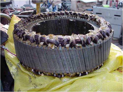
...........oztules Village idiot...or... just another hack out of his depth |
||||
| The Back Shed's forum code is written, and hosted, in Australia. | © JAQ Software 2026 |
