
|
|
Forum Index : Windmills : Messing with the Ceiling Fan - Advice?
| Author | Message | ||||
| floodrod Regular Member Joined: 08/07/2009 Location: Posts: 70 |
While my F&P Windmill is waiting on town permits, I decided to see if I could modify a ceiling fan motor using odds and ends lying around the house.. 
So I begun hunting the house for things I can use and I decided on dremmeling the bottom out of an old metal dog water bowl. I hacked a hole in the bottom for the fan bearing/shaft to come through the dog bowl fit over the armature with a little room to spare. I was able to squeeze round neos between the dog bowl and the outter metal housing. 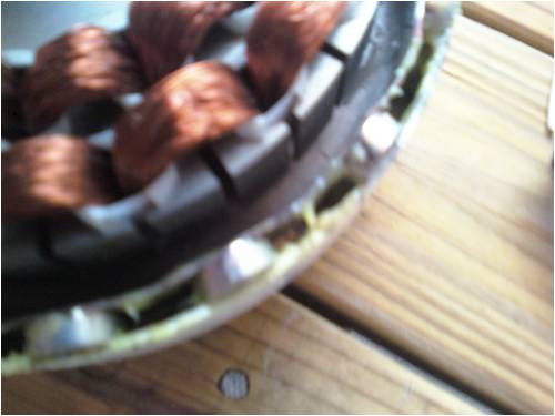
The motor has 16 poles, so I used 32 neos.. I aligned each pole with a row of two neos. I brushed on some extra epoxy I had sitting around and filled up the gaps with clear RTV silicone to make a rubber-like form in all the spaces. The upper magnet sticks out almost 1/2 way to the armature center point, but the magnetism is definitely skewed more towards the front end. When running a test magnet inside to feel the strength and verify polarity, the field through the dog bowl is very strong. It pushes my hand to the middle of the motor shell. The magnets go + - + - etc. I don't feel any cogging. Maybe a little, but it spins easily. When I short all the wires together, it gets much tighter. If I spin the outer shell while the shaft's in a vice, the shell might make it around 1.5 revolutions if it's shorted. If it's not shorted, it will spin maybe 6-8 revolutions. The motor is 2 phase, it has 4 wires. I just guessed and took the red and white and threw a multimeter on them. When I hand spin it I can get over 50 volts AC coming from it and I felt a shock. The other set of wires have relatively the same power. I hooked up 1 small light bulb (like the size of a christmas tree bulb)and I can get it to light up almost fully while hand spinning. This is with no rectifier and only 1 phase. When the glues are fully set I will rectify it and count rpms as I watch the charging voltage and amperage. But from what I describe, can I get any usable power from this setup? |
||||
thaelin Newbie Joined: 14/02/2009 Location: United StatesPosts: 4 |
Now that's refreshing, new use for old junk. I see many of these go by and looked at the coil forms. Considering the size of wire used in them, I would not foresee high amps as output but you could rewire it (UHHHH). One other point I would be curious on is how you intend on wireing up the two different sets of coils. What I mean is the way the coils are wrapped on the form. Just wondering how the coils will react to the passing mags. Anyhow great idea. I am still trying to find a F&P here stateside. I got a quote for one at $290 US and that is just for the stator/mag ring only. |
||||
| Gizmo Admin Group Joined: 05/06/2004 Location: AustraliaPosts: 5182 |
Sounds like a fun project. If its lighting a light bulb, then its making power. You wont really know how much until you connect a rectifier and battery. The battery current will give you an idea. The wire is very fine, so dont expect too much, maybe a few watts. Buts its a good start. To get more power, you would have to move the magents much closer to the coils, and also rewire the coils into parallel, or a series parallel, configuration. Moving the magnets closer gives more power, but also more cogging. I played around with a ceiling fan a few years back. I didn't make a lot of power, but I learned a great deal. Glenn The best time to plant a tree was twenty years ago, the second best time is right now. JAQ |
||||
| floodrod Regular Member Joined: 08/07/2009 Location: Posts: 70 |
Thaelin, I'n in PA and got my F&P from Randys Workshop. Google it.. He's great.. Old Junk? I had to steal the water bowl from the dog and replace it with one of our ceramic bowls. I got yelled at by the wife 
I'm not doing any rewinding or any major work on this alternator. If it doesn't produce anything worthwhile, I will either swipe the magnets back or throw a squirrel cage on the shaft and let it spin.. But it would be nice to get something from it because I have a good mounting spot for a vawt along with my hawt coming soon. I have no idea about the coil thing.. I got the idea from a youtube video. This guy has like 3 hours of videos on how he modified his ceiling fan and made a windmill. I will have to go back to the videos after the motor is tested and closed up. We'll see |
||||
| floodrod Regular Member Joined: 08/07/2009 Location: Posts: 70 |
So today I managed to close the shell up and test the output with a drill.. I toned out the leads and attached the two bridge rectifiers. Rigged up another dog bowl with a threaded rod to turn the motor shell. I hooked up the output leads to an old trolling motor as a load. It seems I am getting .6 amps at 44 Volts peak. 26 watts?.. Excuse my lack of fine electrical knowledge, but when I spin it with no load I get 44 Volts. When I spin it with a load, I don't even get 1 volt, but the motor definitely gets a lot stiffer under load. I assume the no-volt readings are because the load is absorbing the power? At this point I am wondering if it is a better idea to just swipe the neos back and junk it, or continue with it. I was unable to count the rpms because it's spinning faster than I can count. Gizmo- Thanks for the fine tips. When I get enough experience, I will try my own windings and maybe make a generator |
||||
| Gizmo Admin Group Joined: 05/06/2004 Location: AustraliaPosts: 5182 |
Hi floodrod What are you using for a load? Glenn The best time to plant a tree was twenty years ago, the second best time is right now. JAQ |
||||
| floodrod Regular Member Joined: 08/07/2009 Location: Posts: 70 |
Tried a Light Bulb and a Trolling boat motor. Very little current when I use the light-bulb, but the trolling motor peaked at .65 amps and made the fan motor much tighter when under load. |
||||
| Gizmo Admin Group Joined: 05/06/2004 Location: AustraliaPosts: 5182 |
To get a good watt figure, you need to measure amps and volts at the same instant, and the best way is with a battery as the load and a couple of multimeters. You have two AC circuits, and these are out of phase with eachother, so you need two bridge rectifiers. If you connect the AC circuits together you'll get less output. Connect the two bridge rectifiers outputs together +ve to +ve and -ve to -ve. Then connect this to your battery. You'll need a amp meter in line to measure the amps, and a volt meter across the battery to get the voltage reading. Then multiply the two together. Let us know how you go. Glenn The best time to plant a tree was twenty years ago, the second best time is right now. JAQ |
||||
| floodrod Regular Member Joined: 08/07/2009 Location: Posts: 70 |
Hi Gizmo... I got some more accurate numbers and two videos demonstrating... The motor can fully light up a 56 watts of light bulbs. This video shows a small light bulb and some rough numbers http://www.youtube.com/watch?v=JLNolxEWuiA This video shows me lighting up a 40 watt bulb. http://www.youtube.com/watch?v=E3xc7RPPsCQ I then hooked up 56 watts with 3 bulbs and could fully power that. I tried for 66 watts, but it didn't light fully. I can take video if needed. Both phases are rectified than the 4 output leads are connected in series after the bridge rectifiers. Based on the light bulb strategy, I can get somewhere between 56-65 watts. Can't narrow it down anymore with my bulb selection. |
||||
| floodrod Regular Member Joined: 08/07/2009 Location: Posts: 70 |
I have great updates! 
Since I was getting decent power, I decided to re-do it all today and do it right.. (or at least better).. So I ripped out all the mags and the dog water bowl and dremmeled everything clean. I went ahead and used 64 neos (two double stackers X 16). I got them super duper close to the armature. 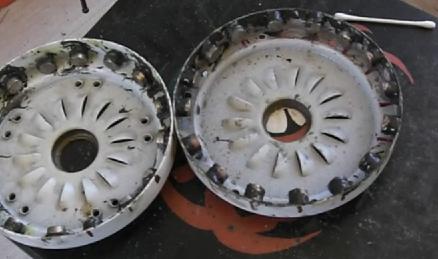
I made a mount by slop welding a 9/16 fine thread nut to a galvanized flange. The wires now run through the mount. I followed through by using spray foam insulation to fill the gaps. 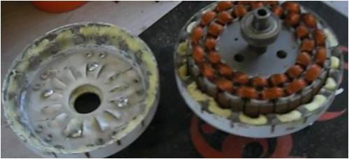
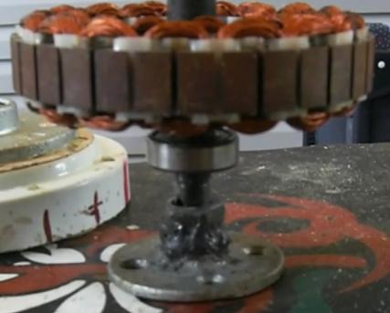
I closed her up and connected her to a 220 watt light bulb load. (100 watt flood light and 2 60 watters). Both phases are bridge rectified and connected + to +, - to -. Before I even get close to full drill force, the 220 watt bulbs max out. 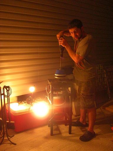
It can push out more I am sure, but I am out of bulbs.. The case actually has enough room for another 32 magnets for a total of 96 magnets. But I didn't take it that far and I am out of magnets:) There is definitely some cogging happening.. I am contemplating if I should dremmel the magnet edges to decog it. Now I am hoping this will make a nice vawt generator in the end |
||||
| joedupont Newbie Joined: 25/08/2009 Location: United StatesPosts: 1 |
Bravo...how much do the magnets cost? I want to make one of the units for a water wheel. keep up the good work! leaving the earth better than we found it. |
||||
| floodrod Regular Member Joined: 08/07/2009 Location: Posts: 70 |
A few years ago I bought the magnets from ebay. I forgot how much they cost but it's wasn't bad. I bought like 100 of them for $50 or something.. But if you are going to try this, definitely get the ceiling fan motor first and measure the thickness of the metal ring that you are taking out. You can then use that measurement to find the perfect sized neodymium magnets. Just remember you need to get 16 magnets around the inside of the shell. I have some more video showing load tests and watt tests. This video shows the process how I modified the motor right through to a 220 Watt test. http://www.youtube.com/watch?v=icebPwwYC2A This video shows what gizmo suggested.. Hook up 2 multimeters to get amps and watts. http://www.youtube.com/watch?v=5QrYf63NUdo Now for my next questions.. The generator is pushing almost 200 volts but my controller is going to be calibrated to divert to dumpload at 28 volts for a 24V battery bank. It seems like anytime the mill spins nicely the watts will be to high and go right to the dump. Can someone point me to a reference that details techniques to stabilize this voltage to be more in the 25V range? |
||||
oztules Guru Joined: 26/07/2007 Location: AustraliaPosts: 1686 |
Replace the light globes with the 24v battery. The battery will clamp the voltage to it's own charge state. It will be highly unlikely that you will need a dump load for some time. I expect maybe 1-2 or so amps running on the drill into that battery (less than 28v). I expect a lot less on a vawt. I have a hunch that you won't require a big dump load. The dump will only come on when the battery reaches 28v or so.... you won't see any higher voltages... it will be clamped to the battery volts. Hook your gear up to the battery, and use your meters as you did on your video .. maybe 50W will be available off the drill. ..........oztules Village idiot...or... just another hack out of his depth |
||||
| floodrod Regular Member Joined: 08/07/2009 Location: Posts: 70 |
Oztules- Thanks, I think I follow.. I hooked up 1 12V deep cycle marine battery with the meters as you suggested. 12 volts for now, not 24 yet. Before the test, the battery read 12.2 Volts. When I drill spin it, I get 13.6V at 1.9 Amps. Roughly 26 watts. Now is this my actual amp rating, or is it just that the battery is loading it to 26 watts? If I hook up a bigger battery bank, will the watts go up? |
||||
| Tinker Guru Joined: 07/11/2007 Location: AustraliaPosts: 1904 |
Only if your drill can supply more input power. Try hooking up a 12V load (like a car spotlight ~ 100W) to your battery at the same time. You will then see if you can get more charging current, no need for a bigger battery bank. Klaus |
||||
| oztules Guru Joined: 26/07/2007 Location: AustraliaPosts: 1686 |
Floodrod, The battery puts a low impedance load on a high impedance alternator... full of armature reactance and leakage. It will try for somewhere near the 2A mark at best, and at a potential of whatever the battery pack is. For 24v, your looking at 28v@1.8A perhaps... or around 50 watts. As you have discovered with your lightglobe test, if the load is a higher resistance/impedance , you start to match the alternator to the higher impedance load, and your watts look so much better. Unfortunately, without a buck converter that would match your high impedance driver to the low impedance load then for your 24v bank 50w will be about the limit. If your frequency is over about 25hz, (and I think it is off your drill), then you could try a few transformers (240v:48v etc) to match the load up.... more experimental than useful at this scale I think. ............oztules Village idiot...or... just another hack out of his depth |
||||
| floodrod Regular Member Joined: 08/07/2009 Location: Posts: 70 |
Tinker- I will try th2 12V spotlight as you suggested. I actually have a 12V at about 100 watts.. Even if it does no good, I would like to see it in action for a better understanding.. Oztules- Your number predictions have been like spot on.. I'm reading up on it now |
||||
DaViD Senior Member Joined: 14/01/2009 Location: United StatesPosts: 120 |
Hi floodrod, I messed around with a fan like yours and I got 60 watts in a 24v system @ around 250 rpm. It was on a hawt type that had really bad cogging. So much that it had to be started by hand. I didn't try a vawt because i didn't think I could get the rpm's I would have to have. So i'm interested if you are going to try a vawt and would like to know the outcome if you dont mind.  If your not living on the edge your taking up to much space! |
||||
| floodrod Regular Member Joined: 08/07/2009 Location: Posts: 70 |
Oztules- Thanks for that great explanation. I grasp that now and realize the coil wire size is capped at under 2 amps regardless of voltage. My expectations are becoming more realistic now. When Hooked up to a deep cycle battery, I get 6.6 Watts at 125 rpm. I have the video posted. You can jump to about 6 minutes if you want to skip the BS. I can peak it at about 24 watts, but the vawt will never go that fast. DaVid- Cogging.. I just dremmeled the edges of the neos today in attempts to decogg it. Feels like it worked. If there is interest, I will keep it updated. http://www.youtube.com/watch?v=4zNmO34QPYk |
||||
| DaViD Senior Member Joined: 14/01/2009 Location: United StatesPosts: 120 |
Floodrod, Did you make a small jig to grind the angles on your magnets or just eye-ball it? Some time ago I played around with HDD mags (cutting in half, grinding etc.) a simple jig works great to bevel the edges. Also I used running water to keep them cooler while grinding. Everythings looking good. Keep posting the vids it's useful for the people new to this. Nice work! If your not living on the edge your taking up to much space! |
||||
| The Back Shed's forum code is written, and hosted, in Australia. | © JAQ Software 2026 |
