| Author |
Message |
oiko
Newbie

Joined: 31/08/2009
Location: FinlandPosts: 4 |
| Posted: 06:41pm 30 Aug 2009 |
 Copy link to clipboard Copy link to clipboard |
 Print this post |
|
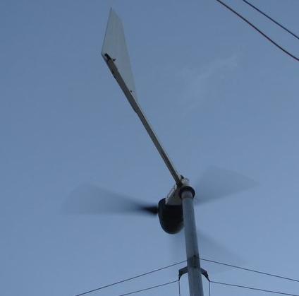
I'm a first timer when it comes to diy wind. I'm planning to build a standard three phase axial flux hawt with a 12 magnets per rotor and 9 coils in stator. The goal is to build about 1-1,2m diameter turbine that charges 12v batteries.
The question I have is the required magnet size. I'm considering N42 grade 40x10x5 mm magnets, will they be strong enough to get enough voltage out at reasonable rpm and coil turns? Reasonable being not very loud and wires being able to carry enough current for a turbine that size (maybe 100-250W electric power at good winds if I calculated right).
As I understand, smaller blade diameter = more rpm with the same wind and tip speed ratio = higher voltage for the same (turns)*(magnetic flux). So I wouldn't need to quadruple the turns in the coils, when I'm using 1/4th the magnet strenght compared to the famous 1kW design, to achieve the same voltage? The amperage is lower ofcourse.
Still a long way to go and lots of questions to ask, but thats the biggest one at the moment.
Edited by oiko 2009-09-01 |
| |
GWatPE
Senior Member

Joined: 01/09/2006
Location: AustraliaPosts: 2127 |
| Posted: 01:57am 31 Aug 2009 |
Copy link to clipboard |
Print this post |
|
40mm x 10mm x 5mm magnets, make for a fair amount of excess wire in the coils. more efficient magnets would be round, 30mm dia x 5mm thick. Coils would be round, with approx 30mm internal hole. turns and magnet spacing adjusted for cutin rpm for 12V. probably only 20 turns per coil needed. This will be a high rpm machine.
Gordon.
become more energy aware |
| |
oiko
Newbie
Joined: 31/08/2009
Location: FinlandPosts: 4 |
| Posted: 10:33am 31 Aug 2009 |
Copy link to clipboard |
Print this post |
|
Thanks for the advice, the efficient use of coil wire didn't come to mind when thinking of magnet shape. Found out that round magnets and coils tend to give a cleaner sine wave too now that I've had the time to go though the forum a bit more.
Could you suggest some reading for scaling designs up and down as it is hard to really find any useful reference figures or models. I've found some academic papers on the matter but understanding them would require a lot of time and diving deep in to my math/phys books and even then wouldn't necessarily be very practical for diy purposes. Building one to experiment with is propably the best way to learn the scaling and tuning I guess, but some sort of reference would be nice building the first one.
Any guesstimates on how thick of a iron plate a mill of this size needs on the rotors to minimize the flux leakage? I don't really have the equipment to cut thick steel.
Edited by oiko 2009-09-01 |
| |
niall1

Senior Member
Joined: 20/11/2008
Location: IrelandPosts: 331 |
| Posted: 01:13pm 31 Aug 2009 |
Copy link to clipboard |
Print this post |
|
hi Oiko
as a rough guide the rotors should be at least as thick as the magnets ... so for the 5mm mags a 5/6mm rotor should be pretty close ...there shouldnt be any magnetic effect on the back of the rotor...using thinner disks might allow this leakage ....plus potentialy physically weaken the alt...(possible flexing)...
with the rotors it is tempting (and maybe best) to bite the bullet and go to a machine shop , although prices can vary.....
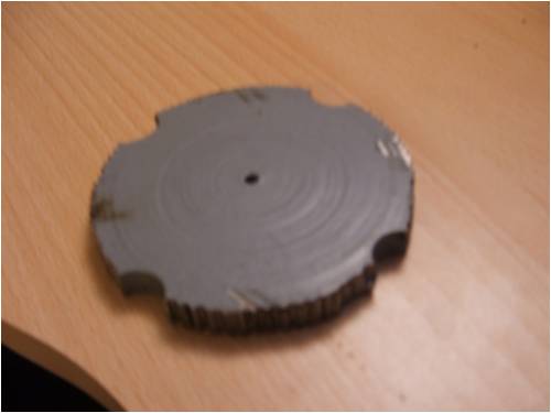
the centre of the rotor below was cut out by drilling around first with a 3mm bit (more than one...  ..) and gently jigsawing it out , the cut can be cleaned up afterwards ..) and gently jigsawing it out , the cut can be cleaned up afterwards
you do loose the will to live doing it
.....but it is an option at least for the centre holes
 Edited by niall1 2009-09-03 Edited by niall1 2009-09-03
niall |
| |
oiko
Newbie
Joined: 31/08/2009
Location: FinlandPosts: 4 |
| Posted: 09:20am 04 Sep 2009 |
Copy link to clipboard |
Print this post |
|
Ended up cutting the rotor back plates from 2-3mm stainless steel that I got my hands on for free. Propably isn't enough to eliminate the leakage but I'll add another one on the back of the rotor later if necessary and if I still have the time and motivation to cut another pair.
Got to admit that making these plates is a lot of work without good tools. Took a while with a angle grinder(?, anyways the hand wielded power tool with spinning abrasive ceramic disk), a light drill bench with too small drill bit and a couple of metal files. I can well imagine losing the will to live if I had to cut a plate as thick as you niall did with a drill  . Having those plates made in a machine shop is tempting if I ever end up making another axial generator. . Having those plates made in a machine shop is tempting if I ever end up making another axial generator.
I'll be posting the results once I get the mill built but that might not be before spring as I haven't got the time or access to a workshop during the semester.
Thanks to everyone here at the forum for lots of useful info. This is the best dyi wind resource online I've found so far. |
| |
GWatPE
Senior Member
Joined: 01/09/2006
Location: AustraliaPosts: 2127 |
| Posted: 01:13pm 04 Sep 2009 |
Copy link to clipboard |
Print this post |
|
Just a question? Is the stainless steel Ferro-magnetic?
The backing plates guide the flux from one magnet to the other. Mild steel, or soft iron is the ideal material. You could attach the rotor magnet rings, made from mild steel, same thickness as the magnets, to the stainless steel rotor plates. I made my first unit with aluminium plates, with iron rings bolted to it. All Mild steel is a lot easier.
I think that you may have missed something in the design of these alternators.
Gordon.
become more energy aware |
| |
niall1
Senior Member
Joined: 20/11/2008
Location: IrelandPosts: 331 |
| Posted: 02:42pm 04 Sep 2009 |
Copy link to clipboard |
Print this post |
|
mmmmm.....as Gordan pointed out (and i didnt.....) the rotors need to soft iron or steel.....
another suggestion might be the old otherpower approach using old car brake disks
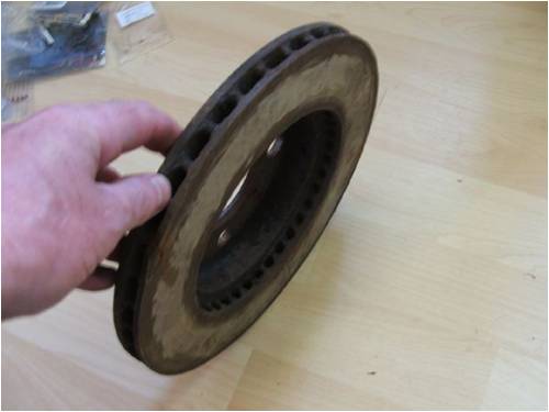
2 front disks and a rear hub would be needed , assemble it with 4 lengths of all thread ..this way maybe you could just concentrate on your stator ..i never tried one but there should be some reading on otherpower on the pros and cons
Edited by niall1 2009-09-06
niall |
| |
oiko
Newbie
Joined: 31/08/2009
Location: FinlandPosts: 4 |
| Posted: 08:25pm 05 Sep 2009 |
Copy link to clipboard |
Print this post |
|
Yeah, I knew that the back plate material had to be ferromagnetic to guide the flux, but completely forgot to check if the stainless steel was ferromagnetic or not. Just thought "meh, steel is steel, it might be sub-optimal, but free steel is free". Also I just wanted to get building right away so I sileced that silent nagging on the back of my head.
Stainless steel apparently has a lot of chromium and nickel alloyed in it and iron content might be something like 50%. So the resulting alloy isn't that ferromagnetic. Live and learn I guess.
Low carbon steel = less magnetization and ability to contain more flux before reaching saturation compared to higher carbon content, right? And easier to work with.
Good thing I didn't yet cast the magnets on the backplate with the resin. I guess I'll just have to find some soft iron or mild steel. Less enthusiasm, more thinking before doing Edited by oiko 2009-09-07 |
| |
