
|
|
Forum Index : Windmills : Current Control
| Page 1 of 2 |
|||||
| Author | Message | ||||
| turnymf Regular Member Joined: 04/10/2008 Location: AustraliaPosts: 84 |
I have been thinking about current control for a small lenz2/fp mill What I would like to do is control the current available to the battery according to rpm of the mill I was thinking of using a scr based circuit with a hall effect for rpm info The reason for my interest is that I would sooner charge at 24v/ .5 amp (for an example) in low wind than to have the back emf of the fp stall the mill Once the rpm is up then lift the current Can someone point out any major flaws on the thought or any comment, suggestions? 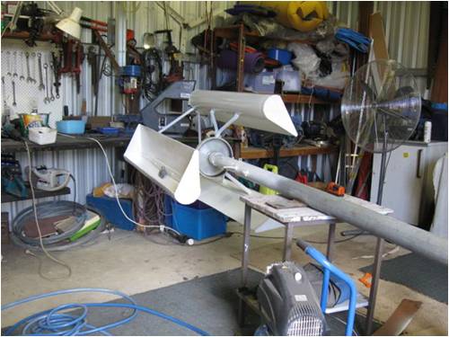
These are the wings at the moment, but they are too heavy so I am going to redo them and upscale a little cheers |
||||
| Tinker Guru Joined: 07/11/2007 Location: AustraliaPosts: 1904 |
You most likely need not to worry about that with your Lenz2. It will not deliver much more than 0.5A @24V in low winds. Mine needs at least 10 knots of wind before it spins fast enough to show any current on the 0-5A meter to the 24V battery bank. If your wings are well balanced then their extra weight would just increase the initial inertia to start turning a tiny bit. I hope you did not try to test that with the pedestal fan I see in your picture  . .Klaus |
||||
| turnymf Regular Member Joined: 04/10/2008 Location: AustraliaPosts: 84 |
Hi Tinker Of course I have spun it up with the fan, how could I not? It is however in that position to balance the blades I am only concerned with the weight on the bearings If the battery is low enough to draw current the mill cannot produce in light wind, then I would imagine it will stall the rotation The intention is to limit the current draw on the windings depending on rpm I don't really care if it only charges at 50ma in light winds, every bit helps and small current is better than no current This idea came from my fp pedal machine Put 300w lamp on and it,s a battle to get going Put 60w lamp on and it's much easier The idea may well be flawed, but I can't see it at this stage, hence my post cheers |
||||
| GWatPE Senior Member Joined: 01/09/2006 Location: AustraliaPosts: 2127 |
Sounds like a perfect candidate for a capacitor voltage multiplier. As long as the alternator is rewired for an output voltage where cutin is achieved at about 1/2 of max rpm or so. Gordon. become more energy aware |
||||
| turnymf Regular Member Joined: 04/10/2008 Location: AustraliaPosts: 84 |
Please excuse my ignorance here I have read the word cutin mentioned many times but haven't been able to get a handle on it Does this mean when the coil voltage reaches desired output voltage or is it a LC circuit resonance type thing? |
||||
| turnymf Regular Member Joined: 04/10/2008 Location: AustraliaPosts: 84 |
This is where my head is at |
||||
Greenbelt Guru Joined: 11/01/2009 Location: United StatesPosts: 566 |
Does this mean when the coil voltage reaches desired output voltage Yes. Cutin is the minimum voltage that will charge your battery. Your system voltage + about 2-volts. Time has proven that I am blind to the Obvious, some of the above may be True? |
||||
| GWatPE Senior Member Joined: 01/09/2006 Location: AustraliaPosts: 2127 |
In the simplest instance and given this is a VAWT, You could simply add 6 series caps, of approx 470uF and 300VDC in a back to back arrangement. This will take the load OFF the alternator and allow the windmill to spin up. The power output will be proportional to RPM. The cct you post is hard to read, but you will need 1 per phase with an SCR. I think this will only provide half wave rectification as well. Gordon. become more energy aware |
||||
| Gizmo Admin Group Joined: 05/06/2004 Location: AustraliaPosts: 5182 |
Yeah I agree with Gordon, I think adding the caps would give you a little extra power at low wind speed. Hey Gordon we need to document the cap circuits. Will send you a message. Glenn The best time to plant a tree was twenty years ago, the second best time is right now. JAQ |
||||
| turnymf Regular Member Joined: 04/10/2008 Location: AustraliaPosts: 84 |
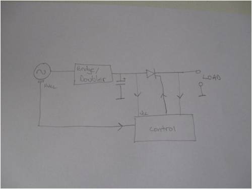
Thanks fellas I hope this picture makes it clearer (my drawing sucks but it's better than what I can do with paint), it is a block diagram and a roughy at that The rail is dc before hitting the switch(scr in the cct) I would imagine that the trigger would pulse which would pulses the output What I want to do is to softly apply the load/magnetic brake (so to speak) until higher rpm is achieved by the wings Thanks for any input 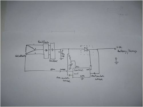
|
||||
| GWatPE Senior Member Joined: 01/09/2006 Location: AustraliaPosts: 2127 |
The SCR won't turn OFF in this arrangement, until the current drops to zero, ie windmill stops. Gordon. become more energy aware |
||||
| turnymf Regular Member Joined: 04/10/2008 Location: AustraliaPosts: 84 |
True Triac or gto scr then maybe Probably even get away with a good old 2n3055 |
||||
| GWatPE Senior Member Joined: 01/09/2006 Location: AustraliaPosts: 2127 |
Series caps will perform a similar task without any control system, power supply or switching device. What expected rpm are you going to have, and what alternator config? This is a 24V setup. What F&P stator? I used a rewired series80 2s7p with a doubler on 24V. This had a reasonably high cutin rpm on 24V. I think 250rpm. 6 x 470uF back to back 180VDC caps will easily pass 200W in a series cap arrangement on a F&P spinning at 350rpm. The cap size will affect the loading. Smaller caps[lower capacitance] will reduce the loading and allow the rotor to spin up more easily. I would use the SCR for other purposes like an over voltage/rpm electrical brake system. Gordon. become more energy aware |
||||
| Tinker Guru Joined: 07/11/2007 Location: AustraliaPosts: 1904 |
This is where I see a flaw in your idea: A lamp load does *not* behave like a battery load. A lamp load demands power from the instant the alternator turns. A battery load demands power only once the alternator voltage goes above the battery charging voltage. Your 24V battery requires at least 27.5V to start charging. Try it with your horizontal fan set up, connect your battery and see what's happening - it may help to see what I'm saying. Klaus |
||||
| turnymf Regular Member Joined: 04/10/2008 Location: AustraliaPosts: 84 |
Thank you tinker, I think I get it No current draw from battery until cutin voltage achieved, so no magnetic braking Thanks to Gordon too I wouldn't imagine I'd get to 350 rpm unless in a gale I wasn't going to modify the stator at this stage, just run the 3 phase down the pole then do the rectify/double/regulate thing from there I do have a stator modified for 7 phase with a new hub, but I have put it away until I get braver about my setup The battery is 8 six volt fork lift cells I have some 10p20 and 10n20 mosfets which on reflection would better suit swithing Tracs wont work of course because they are for ac switching My cro has died(some where in the hv side, I have rails and heater but nothing at the ulta), anybody got a schematic for a old hung chang 5504? cheers |
||||
| nitecrawler1958 Newbie Joined: 09/10/2009 Location: United StatesPosts: 1 |
would a delco 10-SI 24vdc voltage regulator work? P.N.D30-1 WAI has lot's of stuff. Sorry if I'm wrong! This is my frist Post Steve |
||||
| GWatPE Senior Member Joined: 01/09/2006 Location: AustraliaPosts: 2127 |
I missed this before. Without a stator rewire, the only F&P suitable for your arrangement would be a 100S wired in delta. Capacitor voltage multipliers are not regulators, but a novel way of load matching a windmill alternator to a battery loading. When you get to a rewire, then cap multipliers will allow a better matching of the load to the windmill. Gordon. become more energy aware |
||||
| turnymf Regular Member Joined: 04/10/2008 Location: AustraliaPosts: 84 |
Howdy fellas I have finally got my lenz2 up It's a 80 series(stator pole twist) original wiring in star with the 3 phase run down the pole Only light winds here to day The lenz got up to about 60 or so rpm going by the 'one one thousand, two one thousand, three one.....method The 3 phase is going into a bridge in the normal manner then the dc rail is sitting on a 6800uf 250v electro with a dvm and a couple of lamps(12v+250v)close by but not connected I did notice that whenever it spun it would ,of course, show volts at the cap that climbed with the rpm The max volts I saw was about 60 (cap only)at the max rpm I have seen to date At about 50v I can apply the 12v 50w lamp to the cap and crackle crackle, bright light then dvm shows 0v I can apply 240v 60w lamp and the elements burn orange and the volt drop is much slower the with the 12v one My first little bit of wind power, hip hip I know there is a miss match of volts and this is proof of some power The mill went start/stop all day and was a little noisy at certain rpms Appyling a lamp load reduced rpm to near a stall but not having a steady breeze and not much of that it wasn't a surprise I would expect that some sort of charge could be gathered on such days by having only the cap as a load and pulsing the load on and off it according to it's charge state and/or rpm This would allow the rpm to be at it's max more on soft days I know I am talking about low power but every little bit helps I understand cutin now, thanks If I was to apply a battery load today, with the setup so undeveloped and all, the mill would have remained still, staggered a little once in a while perhaps, but still Heres a pix of it 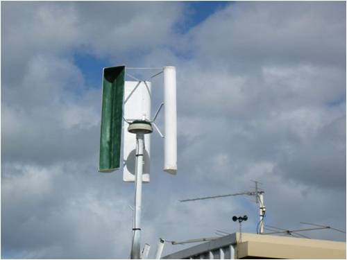
Cheers for reading and go FORD at Bathurst |
||||
| Tinker Guru Joined: 07/11/2007 Location: AustraliaPosts: 1904 |
Congratulations on getting the Lenz2 running. I'm not sure you quite understand the "cutin" part yet. It *is* related to the voltage your wind generator has to produce to be able to charge a battery. So your last paragraph makes no sense. Please do try it with a battery connected. You need no capacitor, just 2 bridge rectifiers wired up to accept 3 phase AC. Your battery will limit the generator voltage to the battery terminal voltage - disregard what you measured with your lamp load. With that generator and a decent (car size) battery you have no problem overcharging it unless you have a gale for hours on end. Connect an Amp meter in series in the lead from the battery to the rectifier (polarity is important unless the meter is digital in which case it may read negative) and see what charging current you get. That is the only real way to test your generator, flickering lamps are not ideal at all - their resistance (load) changes drastically as the element heats up. When your battery gets fully charged (13.5 - 14V at the terminals) connect a load to it to give your generator some work without overcharging the battery. Do read up on the part where it says that wind generators should always have a load connected to avoid runaway in high winds. Klaus |
||||
| Tinker Guru Joined: 07/11/2007 Location: AustraliaPosts: 1904 |
"I would expect that some sort of charge could be gathered on such days by having only the cap as a load and pulsing the load on and off it according to it's charge state and/or rpm " That is not a good idea IMO, I think you completely misunderstood the function of the capacitors Gordon mentioned in his post above. Klaus |
||||
| Page 1 of 2 |
|||||
| The Back Shed's forum code is written, and hosted, in Australia. | © JAQ Software 2026 |
