|

|
Forum Index : Windmills : Questions about F&P and 3 pha
| Author | Message | ||||
| Rodney Newbie Joined: 10/10/2009 Location: AustraliaPosts: 5 |
Hi again, I have some more questions to ask please. As I have said before I like to know how snd why before I start anything. I have been reading about the F&P wired in 3 phase, and have read that 3 phase has a ratio of 3/4 (3 poles or coils to 4 magnets) why is this, does this only apply to F&P stators and what would happen if you never had that ratio, like if you had more then 4 magnets to every 3 to every coils (maybe not in a F&P). Thanks' Rodney |
||||
oztules Guru Joined: 26/07/2007 Location: AustraliaPosts: 1686 |
Rodney, click on this link from Scoraig wind Watch the North and South pole (black and grey) magnet positions versus the coil positions carefully Notice how for a particular phase colour (red, blue or yellow coils), that for the three coils of any one colour at a certain time, there will be a grey magnet over one coil leg, and a black magnet over the other opposing coil leg... this will be the maximum voltage being generated in this phase, as we rotate, the next colour lines up with N and S over each leg, and on to the next colour. The minimum voltage (EMF) generated in any phase is at a minimum when a magnet is centered over the coil, and the legs are exposed to equidistant magnets N and S so no flux moving through the leg at that point. The same thing happens to each 3 coils in a group /phase simultaneously, and happens sequentially to the phases..... on and on.... Can you now see why the geometry works for the 3:4 combination Below the coil/magnet stuff, you can watch the voltage rise and fall (positive and negative of each phase) .... check it against the magnet positions for any phase you are watching..... slowly it will make sense. [quote] I have been reading about the F&P wired in 3 phase, and have read that 3 phase has a ratio of 3/4 (3 poles or coils to 4 magnets) why is this, does this only apply to F&P stators and what would happen if you never had that ratio, like if you had more then 4 magnets to every 3 to every coils (maybe not in a F&P). [/quote] You should now be in a position to answer your own question. ............oztules Edit: Ignore the thickness of the voltage lines at the bottom. The blue one stays thin on the negative transition... making one think there is something intrinsically different.... but all phases are symmetrical. The length is correct though. Village idiot...or... just another hack out of his depth |
||||
| Rodney Newbie Joined: 10/10/2009 Location: AustraliaPosts: 5 |
Hi Oztules, Thank you for replying and the link it was very helpfull, So brining it back to the F&P stator, each side of the coil in your animation would be the same as the poles you rewire together on the F&P stator which would line up with a north and south pole. Is this correct. javascript:AddSmileyIcon('  ') ')
Thanks Rodney  |
||||
oztules Guru Joined: 26/07/2007 Location: AustraliaPosts: 1686 |
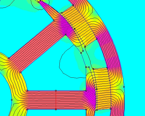
For the salient pole machines (F&P) it is opposite. For an axial, the magnet over the center of the coil is EMF min, for the F&P, the magnet over the top of the pole tooth (center of coil?) is EMF max. Stop the display with a black magnet centered over a coil center (ie tooth for F&P). The other blacks are over the gaps between pole teeth... EMF min The Grey magnets are all at various positions above pole teeth in this case, and provide the return path.... like this : 
Village idiot...or... just another hack out of his depth |
||||
| Rodney Newbie Joined: 10/10/2009 Location: AustraliaPosts: 5 |
Oztules, Thank you, it's becoming much clearer now. Again thnk you for your time. This site has a wealth of knowlege, good on you all. Rodney |
||||
| The Back Shed's forum code is written, and hosted, in Australia. | © JAQ Software 2026 |