
|
|
Forum Index : Windmills : Magnetic saturation
| Page 1 of 2 |
|||||
| Author | Message | ||||
Highlander Senior Member Joined: 03/10/2006 Location: AustraliaPosts: 266 |
Hi Guys, I think this needs it's own thread as it's pretty complex, and basically determines what these will produce. Megawatt the pole fingers are 4.5mm wide 27mm across and 28mm high, thats to the plastic former. It gets quite meaty inside the former, about 10mm thick ring all the way around I think. It needs to be thrown in a fire to really know. 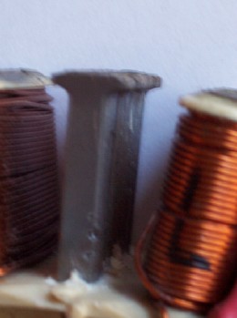 Central Victorian highlands |
||||
Megawatt Man Senior Member Joined: 03/05/2006 Location: AustraliaPosts: 119 |
OK gentlemen, I have done a first approximation calc. But I really need to know now, how wide is the normal air gap in the F&P and what are the dimensions of the iron core at the top where it protrudes from the plastic? The core calculates at 121 sq mm and the top looks like it might be about double that. The error in that assumption is 100%, so I'm looking to supply a better result than that. Equally, the air gap dimension is critical. I'm pretty sure that the 100 stator has 44 turns, that's another input. Megawatt Man |
||||
| Gizmo Admin Group Joined: 05/06/2004 Location: AustraliaPosts: 5182 |
The air gap is 0.5mm from memory. Do you need the inductance of each type? I could measure the inductance of a 60, 80 amd 100 tonight if that would help. Glenn The best time to plant a tree was twenty years ago, the second best time is right now. JAQ |
||||
| Megawatt Man Senior Member Joined: 03/05/2006 Location: AustraliaPosts: 119 |
Hello Gizmo, no, don't need inductance thanks. 1/2 mm is good. The calc goes like this. Knowing the area of the pole piece at 121 sq mm, and the fact that 3.5% Si saturates at around 2 Teslas (or webers per sq metre, all the same) we can calculate the flux in the pole piece in webers. That is the same flux as in the air gap, so knowing the effective area of the top of the pole in the air gap, (a little mucking around here because of fringing effects of the field in air rather than steel)we calculate the flux density in the air gap. Then we use B=muo*H, where B=flux density, muo = 4*pi*ex-07 for air and H is the magnetic intensity in amp*turns per metre. Knowing the length of the air gap l we caculate the Magnetomotive force F=H*l that happens to be =N*amps in amp.turns and knowing N, the number of turns in our coil, we calculate the amps that will cause the flux to be created in the air gap that we started with, that's still the same flux in the pole to just cause saturation. You can see the room for errors, in the area at the top of the pole as compared with the area of the main stem of the pole and the area of the pole piece air gap because of the fringing. Nevertheless, the calc should end up around 10% right and that should be a good enough guide for boys who are measuring things like reduced rate of induction into a search coil at saturation. Re Highlanders later report, about the Ts getting too hot, that's eddy currents and I reckon widening the gaps would reduce it, but I don't know by how much. Maybe the eddy current thing makes it too hard. We need a certain thickness up there to allow a reasonable path for the mag field to get part way across the next pole before leaving the last, via the skew to reduce cogging, but thin enough to discourage eddy. Wider gaps would cause the flux to go down deeper into the poles and I predict would give a better output. I reckon too that since the field would have a better opportunity to do its work on the coils better, it would do a bit less eddy current energy wasting. Megawatt Man |
||||
| Gizmo Admin Group Joined: 05/06/2004 Location: AustraliaPosts: 5182 |
Measured the pole tops. As you ca see from the Highlanders picture the sides of the top are rounded. Even though the picture shows a stator thats been slightly decogged, it looks like there is a slight rounding from factory. The widest part is 10mm, but this drops down to 8.5mm at the very top where the air gap is.The length of the core I measure at 25mm, not including the plastic. 
Glenn The best time to plant a tree was twenty years ago, the second best time is right now. JAQ |
||||
| Highlander Senior Member Joined: 03/10/2006 Location: AustraliaPosts: 266 |
Hi Megawatt, would you like me to cut you out a setion and mail it to you? With the saturation does that change with your wiring, be it 100p compared to 80sp? Central Victorian highlands |
||||
| Megawatt Man Senior Member Joined: 03/05/2006 Location: AustraliaPosts: 119 |
G'day gentlemen, thanks for the measurements. Thanks for the offer of mailing me Highlander, but I don't need it yet. Saturation. What is it? Magnetic materials are made up of lots of tiny call them what you will, crystals, domains etc. They are all held on to one another very strongly. The domains are all aligned higgledy piggledy, but each one of them is a little magnet in its own right. Because they are all pointing all over the place, the material is not a magnet under normal conditions. When you apply a small magnetic magnetic field to the material, some of the little magnets that are each domain strain away from their normal position and come into line with the magnetic field and the material now exhibits the behaviour of a magnet. When we apply a bit more magnetic field, a few more domains strain against their normal attractive forces in the material and they come into line too, and the magnetic characteristics of the material become stronger. This keeps going in a proportionate way, until the number of domains that come into line get fewer and fewer and to get the same effect we would need to apply several times the magnetic force to cause the same increase in the magnetic effects exhibited by the magnetic material. We get to the point where no matter how much of an increase in magnetic force we apply, no further increase in magnetisation of our material can occur. We say the material is saturated. We don't run magnetic machinery into saturaton because of losses, noise, generation of large distorted currents and some other effects. We run it at the highest possible level of magnetic field we can achieve without going into saturation. So saturation is a property of the magnetic material, not of the coils around it. We need to consider the coils only when we are passing an electric current through the coil in order to make the magnetic field that we want the material inside the coil to respond to, in a magnetic way. So if we double the current, we double the magnetisation of the magnetic material but only until saturation. After that, we can whistle Dixie, because we would need huge currents to get any extra magnetisation. OK, now for some calcs. If you look up the magnetisation curves for 3.5% silicon steel, you will see that the magnetic flux density at which the steel becomes saturated is 2 Teslas, or 2 webers per sq metre. Now the area of the poles in an F&P is 121 sq mm and the effective area of the pole ends and the area of air between the rotor and stator at the end of apole is close to double this. About 250 sq mm actually, but I'll call it double, for the sake of easy maths - and it's near enough for out here in the bush - sorry, near enough for an engineering approximation. That means the the magnetic flux density in the air gap is 1 Tesla. Now for air, it turns out that Flux density B=4*pi*exp-7*H, where H is the magnetic flux intensity in a unit called amp*turns per metre. The 4*pi.... stuff is the magnetic permeability of free space or air and it's not a very big number. Amp*turms re metre, that's the number of amps flowing in a coil of N turns, generating a magnetic field in an air gap 1 metre long. Now we reckon that the air gap in a F&P is only 0.5 mm long, so we will get that number down a lot. This is getting heavy. A couple of steps later in the calc, shows that the Magnetomotive force to produce 1 weber per sq metre in our air gap of 0.5 mm is close enough to 400 amp*turns. So for our 100 stator, with (I think) 44 turns per coil, we need 400/44 amps amps or 9 amps to almost saturate the pole. I think the 80 stator has 115 turns, so to saturate its core, we need 400/115 amps, or 3.5 amps. So there are a couple of numbers to check out by experiment. If my main assumptions were close, the currents given will also be close. Some qualifications though. I assumed: air gap is 0.5 mm; effective area of top of pole piece is 240 sq mm - good enough for a first approximation; 44 turns per pole on a 100, 115 turns on an 80 and area of poles in a 100 and 90 are the same. Whew. Megawatt Man |
||||
| Highlander Senior Member Joined: 03/10/2006 Location: AustraliaPosts: 266 |
Hi Megawatt, I thought this was going to get complex. Basically if all the input data is right we should get a max of 3.5 amp times 42coils =147amps or 1764 watts at saturation for an 80 stator. Is that right? Central Victorian highlands |
||||
| Megawatt Man Senior Member Joined: 03/05/2006 Location: AustraliaPosts: 119 |
G'day Highlander, I guess that would be basically right. But your calc uses 12 volts as the output and there would be some voltage drop and this would reduce the overall output. On the Eccoinovation site, mention is made of a maximum output of 1400 watts and in another place they say that the max current on a 80 stator is 3 amps and then they go on to say that 3 amps may be too much because of the heat that would be generated in the coils. We don't want to burn them out. If I imagine a max coil current of 3 amps and a 1 volt drop at that current but I use the rest of my figures we get an output of 1386 watts theoretical. So if tey are correct, my numbers should not be too far out. But there's a along way to go yet. I have worked out those current values to give the experimenting boys some figure to work around. We need the practical test to show just where saturation occurs. Let's say it's 3 amps for argument's sake. Then we need to check whether 3 amps continuous will heat the coil up excessively and burn it out. It ought to be able to stand 75 degrees C inside, but less is better. When we know the saturation current, I can back calculate to find out which neo (if any - maybe F&P's strip magnets are exactly right) is needed to provide just short of that level of magnetisation and then start on speeds that give useful output voltages at the max current the coils can stand. Megawatt Man |
||||
| Feral Newbie Joined: 03/12/2006 Location: AustraliaPosts: 39 |
Hi to all, I have read most of the comments on this site and as I have an interest in the FP motor for power generation I have done a couple of very simple tests with the motors and I have dismantled one just to see how it was constructed. It appears that from the educated comments from various people on this site and other sites with people who deal with the FP motor that their is a deficiency with the amount of steel in the core of the coils which limits their output. I am no electrician and I normally deal with flow of sh*t not electrons so I have done some basic tests with a elec drill to power the shaft and only one coil wired to the bridge to run a auto light bolb and Dc measurements taken at different speeds after altering the number of turns in the coil on the 80 series. After removing about 25 turns I increased the voltage to 15 and lost no amps at just under two. I then wired two coils in series and got the same volts at about half speed. From reading other posts it would appear that more steel is required in the core and this can be achieved by taking advantage of how the laminated core is constructed. The core is constructed of about 50 laminations cut into shape, riverted together in six places and then coated with plastic. The steel core is as stated by sombody elese 26 mm thick. If one was to take a complete motor and strip off all of the plastic on one side only on the exposed side ( opposite side to inside hub) and do the opposite to a second motor so that an extra 8mm of steel laminations could be taken from one and fixed to the other. This would then give you a steel face against the magnet of 34mm, about 1-2 mm wider than the magnet of 33mm. The hub would have to be allowed to then come in over the magnets so that the extra steel core thickness is covered and passed by the magnets. I have read on other DIY sites that the generating coil should be just wider than the magnet passing over and this is not how the FP moter is constructed. I have added 4mm to both sides of only one coil so as to do some basic tests again and the hub still fitts on and does not rub on the inside with the steel core face just outside the line of the magnets. I am going to start with 140 turns and work my way down and see what the difference is in volts and amps with auto bolbs as load at different speeds. I did say I am no electrician. I anybody is interested in the results I will post them as some of the information and calcuations in above posts a bit to tecnical and beyond the understanding of most people. Feral |
||||
| Highlander Senior Member Joined: 03/10/2006 Location: AustraliaPosts: 266 |
G'day Feral, good to see someone else likes to tackle the bastard jobs. However If Megawatt's calculations are right we shouldn't need any extra steel in there. I think if anyone gets close to 1000 watts they will be extatic with that. We have to remember that we still need to drive it with blades at normal wind speeds. The more power, the bigger the blade req'd, but we lose revs.Less revs=lower power. The perfect balance is out there, buggered if I know what it is though. I suspect ecoinnovation has got it fairly right as he has done so much testing and has had backing from f&p factory. PS you'll need to use silicon steel if your adding plates to the inner core.I tried that before and found it incredibly fiddly and time consuming. Central Victorian highlands |
||||
| Feral Newbie Joined: 03/12/2006 Location: AustraliaPosts: 39 |
Highlander, from what you wrote in the last paragraph which was, (PS you'll need to use silicon steel if your adding plates to the inner core.I tried that before and found it incredibly fiddly and time consuming.)it appears that you have misunderstood what I had suggested. I did not mean individual small plates of steel, I meant a complete ring of the circular 42 coil former but with the steel laminates 8mm thick in tact. This piece would simply increase the thickness of the steel laminates of former and it would include the circular plastic ends on one side of the formers. At moment I am not looking at using the FP motor for a wind generator as the trees in all directions are thirty mts+ high but there is plenty of wind for most of the year. I am looking at replecating the Adams pulse motor and I am using one of the 42 coils of the FP motor as the generating coil mounted at every 90deg around the magnetic rotor. If this dream fails then it will have to be a 30Mt high mast or tower or more cooking oil from the fish shop in the old genny. |
||||
| Highlander Senior Member Joined: 03/10/2006 Location: AustraliaPosts: 266 |
Ah I got your idea now I thought you were talking about two seperate ideas when you said add 4mm to each side, if you said the ends I would have understood. Silly me 
ps just cut the trees down or just wait for a bushfire  Central Victorian highlands |
||||
| Feral Newbie Joined: 03/12/2006 Location: AustraliaPosts: 39 |
Highlander, I have glued to 4mm layers on either side of one coil only so as to test for increased performance. If their is an increase I will do it the other way that I explained with an 8mm section of the complete ring of coils on one side only. We dont get any bush fires up here as it does rain quite often. In the eleven months I spent their from the start of November last year we received six Mts of rain, not six inches or six feet, 6 Mts. |
||||
| Highlander Senior Member Joined: 03/10/2006 Location: AustraliaPosts: 266 |
Hey Feral, good luck with it. 
After hearing that you should try hydro if your near a creek ecoinnovation sell kits or complete ones. here I wish we had that rain, nasty fires down here, nothing close yet. Central Victorian highlands |
||||
| Megawatt Man Senior Member Joined: 03/05/2006 Location: AustraliaPosts: 119 |
G'day Feral, If you add say 8mm to each coil (plus to the whole spider really) you'll add about 30% to the area of the coil and therefore 30% to the magnetisation you can achieve before saturation. Somewhere else (I think on T-plate failure) I have pointed out two things. First, if you are going to unwind two machines and add some laminations, then rewind the coils, you might as well put the two whole spiders together. You'll get double the pole area and therefore double the magnetic flux before saturation, so you'll generate double the voltage for the same speed, if you put back the same number of turns. So you can get twice the power out, if you have a big enough prop. The Second thing was that you can save yourself all that trouble and put two machines on the same shaft with the same end result. Megawatt Man |
||||
| Megawatt Man Senior Member Joined: 03/05/2006 Location: AustraliaPosts: 119 |
G'day again Feral, just had another look at you post about experimental results. Good work. Here's the gen. Voltage output is linearly dependent on three things. Magnetic Flux in the coil (until saturation occurs) Speed of rotation Number of turns on the coil. That's why I want to KNOW what saturates a core. Megawatt Man |
||||
| Highlander Senior Member Joined: 03/10/2006 Location: AustraliaPosts: 266 |
Hey Megawatt, I don't have all the mergatroid diagnostic tools to measure saturation but maybe we can test the watt output at higher revs I have a spare 2 hp 2 stroke and was thinking of hooking that up just to see how many watts it will do. Is 2 hp enough? Central Victorian highlands |
||||
| Megawatt Man Senior Member Joined: 03/05/2006 Location: AustraliaPosts: 119 |
2HP is close to 1500 watts input. Allow a fair bit for inefficiencies and you are talking 1 kw or more out. I reckon that's about what we need from the F&Ps. More would be lovely but we can always get lateral in our thinking from there. This test won't tell us about saturation lemits, but it would provide valuable info that woud sit nicely on Gizmo's new thread. Megawatt Man |
||||
Pt w/field Matt Senior Member Joined: 24/02/2006 Location: AustraliaPosts: 105 |
hi highlander seen a setup on ebay using a honda 3hp and a f&p on it using 325. to 1 gearing he got 45 amps ,he also had another pulley for 65 amps but didnot mention what gearing for the output,i would go for 2.5 to 1 for a good fast spin 3600rpm devided by 2.5=1440 most stationary motors develope max power @3600rpm. i would do the test but all my motors are down my farm matt down south |
||||
| Page 1 of 2 |
|||||
| The Back Shed's forum code is written, and hosted, in Australia. | © JAQ Software 2026 |
