
|
|
Forum Index : Windmills : A Prop Hub Design
| Author | Message | ||||
Gill Senior Member Joined: 11/11/2006 Location: AustraliaPosts: 669 |
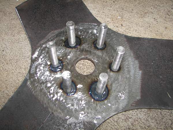
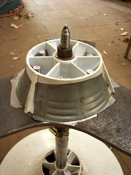
I really struggled to come up with a prop hub for my wind gen. Incorporating the spline was my nemesis. There are few if any suitable designs to pick from. I came up with this use of recycled and other parts so thought to share it in case others are looking for a hub setup too. My hub consists of the F & P agitator spline and a prop backing plate of steel that is held together with studs encased in a polyester resin filler. 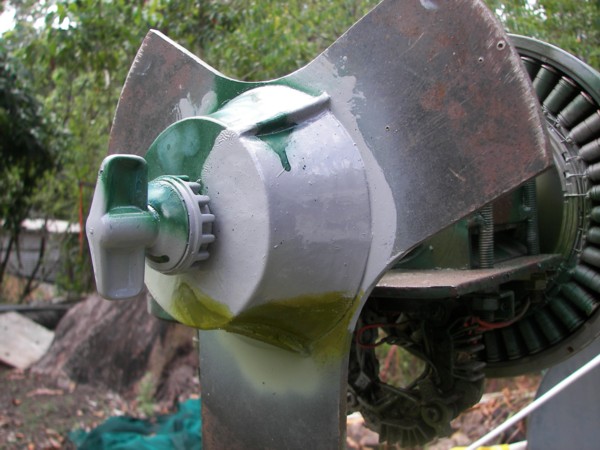
For construction details:- click here Does anyone have a good ideas for a variable pitch prop to suit F & P shaft??? was working fine... til the smoke got out. Cheers Gill _Cairns, FNQ |
||||
Highlander Senior Member Joined: 03/10/2006 Location: AustraliaPosts: 266 |
G'day Gill, well done. I had the same problem and just bought one from trev. It's a nice piece of work and $140 isn't bad for what you get. Plus the 34 degree pitch is already there. He makes variable ones too, $250 click here Central Victorian highlands |
||||
| Gizmo Admin Group Joined: 05/06/2004 Location: AustraliaPosts: 5182 |
Well done Gill, its good to see someone finding more parts in the F&P that can be re-used. Glenn The best time to plant a tree was twenty years ago, the second best time is right now. JAQ |
||||
Pt w/field Matt Senior Member Joined: 24/02/2006 Location: AustraliaPosts: 105 |
hi gill great design butwhy not use a plate on the other side and metal thread bolts and nyloc nuts for more strength,just an idea matt down south |
||||
| Gill Senior Member Joined: 11/11/2006 Location: AustraliaPosts: 669 |
Hi Matt, This design suits my blades which could be likened to a pipe or drum section with a flat trailing edge. I'll call it a 'thin lazy j' shape. Your suggestion would not strengthen this setup. However for someone fitting wooden props with a solid thick root, an added top plate secured using longer studs and nuts would surely be a variation better than my basic design. was working fine... til the smoke got out. Cheers Gill _Cairns, FNQ |
||||
feix62k Newbie Joined: 30/07/2008 Location: AustraliaPosts: 36 |
hi thanks for the ideas could you also just use the metal plate but with 2 of the removable lock plates and spline gears under the agitator and somehow resen the cogs in and bolt 1 on each side of the plate together, you no the lock plate with 5 screws under the agitator just a thought. dont the days seem lank and long when nothing gos right and everthing gos wrong |
||||
| Gill Senior Member Joined: 11/11/2006 Location: AustraliaPosts: 669 |
feix62k, There is usually 6 or more ways to do most things. If you have one that has proved successful for you, by all means present it.  was working fine... til the smoke got out. Cheers Gill _Cairns, FNQ |
||||
| feix62k Newbie Joined: 30/07/2008 Location: AustraliaPosts: 36 |
thanks gill what sort of blades did you use and how did you conect them, really good pics I wish I had kept the agitator now never mind I will just have to search more junk yards dont the days seem lank and long when nothing gos right and everthing gos wrong |
||||
| Gill Senior Member Joined: 11/11/2006 Location: AustraliaPosts: 669 |
I didn't get to fit the blades I'd first planned on. Instead I fitted the fibreglass Chinese blades. Unlike the intended blades, the Chinese blades needed an adapting spacer to fit the aerofoil profile to the flat hub mounting. They also needed tapered washers so as to adequately clamp the root. In addition to this I used Sikaflex as a bedding/adhesive due to the tear away failures others have experienced. Due to blades with no twist having a progressively larger angle of attack as they get closer to the root, I chose a small angle of attack of about 2 deg. which gave a blade angle of about 7 deg. I also modified the blades, but unlike Glenn's, my tapering starts much further out from the root where it coincides with and maintains the blade calculators angle to the tip. The tips and the trailing edges are also reshaped. I am very pleased with the result and performance is better than I expected. As expected from blades with little twist and taper, start up is a little later @ 15 kph and furling starts at 40 kph (15.7Amps). There is no noise at all unless a wind gust abruptly dies, then flywheeling causes the prop to be a driver instead of a driven (a wind gens reverse thrust) and this causes a chopping/whooshing noise until it slows to match the wind again (back-to-front profile as a fan). But back to the prop hub... It's worked really well. Here's some pics from blade mounting to flying. Top view of root. 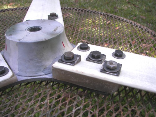
Blade angle. 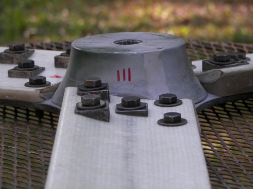
Fibreglass adaptor block. 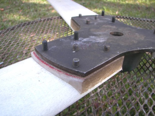
Modified Chinese blades. 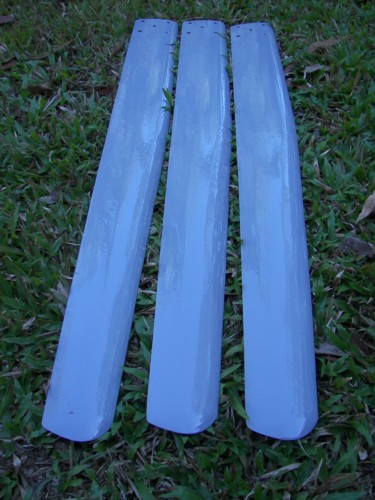
Blades fitted and bedded. 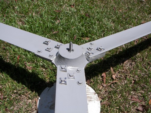
Furling test. 
Paying its way. 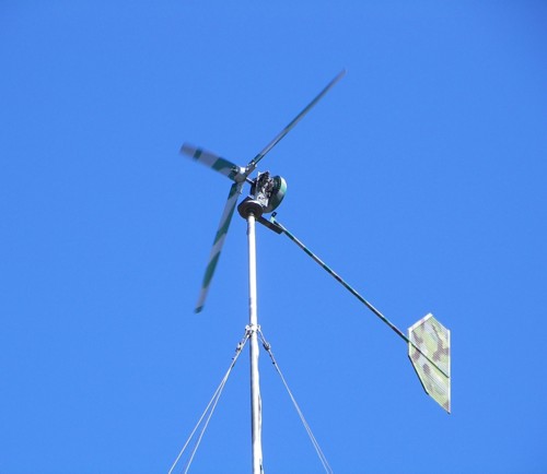
If you plan to use the same type blades, I can give you a brief run down on how I made the adaptor blocks? So I hope that gives you some idea of how it was done. 
was working fine... til the smoke got out. Cheers Gill _Cairns, FNQ |
||||
oztules Guru Joined: 26/07/2007 Location: AustraliaPosts: 1686 |
The smile on your face says it all.... nice job Gill. ......oztules Village idiot...or... just another hack out of his depth |
||||
| Dinges Senior Member Joined: 04/01/2008 Location: AlbaniaPosts: 510 |
Gill, are you sure the tailboom is strong enough ? In the picture with you and the car it looks as if the tailboom is bending quite a bit under its own weight. Either way it's a long and pretty thin arm. |
||||
| Gill Senior Member Joined: 11/11/2006 Location: AustraliaPosts: 669 |
Dinges, Thanks for your concern. Yes, you are right, there is a down curve in the boom but it's deliberate and not bending unduly from tail weight. was working fine... til the smoke got out. Cheers Gill _Cairns, FNQ |
||||
| GWatPE Senior Member Joined: 01/09/2006 Location: AustraliaPosts: 2127 |
Hi Gill, the rotor can only behave this way if there is no load on it. Once I connected the maximiser on my mill, this has never happened. The blades on my mill are always under load at wind energy levels above 3W for a 2m rotor dia. The noise that the chinese blades make was the reason I canned a chinese mill that I was testing. This was prior to my success with a maximiser. Noise is of primary concern to successful use of windmills in suburban residential areas. I could revisit testing of a maximiser on a chinese windmill when bolty gets his flying. Are the blades the pultruded fibreglass type? The chines blades I had, had many small bumps on both surfaces. Did you sand and then refinish your blades after the leading edge mods? PS The camo-scheme adds a unique touch. Is this a 24V, or 12V setup? Gordon. become more energy aware |
||||
| Gill Senior Member Joined: 11/11/2006 Location: AustraliaPosts: 669 |
Gordon, I must disagree the noise is associated with no load on the rotor. This is a standard 12v, 2 x poles in series 3 phase star, times 7. There is no electronics to remove the constant loading as appropriate to the rpm when battery charging. As I see it, TSR drops during the initial onrush of a gust and it takes some period of time for the blades to pick up speed to match the new wind velocity. Conversely, when the wind drops very suddenly the TSR goes very high until the power of inertia in the prop is dissipated by the gen load and the drag of driving the wind. I feel the duration of the noise in unwinding is an indicator of the windmills response time when winding up in a gust. As I have said, there is no noise when winding up no matter how severe the gust, nor is there noise when the wind velocity dies normally. I am aware of the whales fin and it's effect at staving off stall, and I observe this noise to be the other extreme of that. I don't agree there is any absence of load but I know that increasing the gen load at this time would direct the dissipation of the power of inertia to the batteries instead of wasting it by forcing air through. Alas this is an old standard mill and no sophisticated power tracking is fitted. I think the noise is more a characteristic of extreme turbulence at my site and not an indication of poor design. I mentioned it as I felt most would not get this effect often enough to work out its cause. But perhaps I am wrong and some sites fair the same as mine. I can see a maximiser with it's load varying ability is able to capture this wasted energy and in so doing reduce any noise. Other than this and variable pitch, I don't see any remedy.  was working fine... til the smoke got out. Cheers Gill _Cairns, FNQ |
||||
| feix62k Newbie Joined: 30/07/2008 Location: AustraliaPosts: 36 |
Hi gill yes I would be interested in ha rundown on how you made the adapter blocks for the chinese blades thanks Shane dont the days seem lank and long when nothing gos right and everthing gos wrong |
||||
| Gill Senior Member Joined: 11/11/2006 Location: AustraliaPosts: 669 |
G'day Shane, Sorry I didn't take any photos of this part of the prop hub project so you will have to tolerate my sketch instead. The adaptor blocks are made of fibreglass and are made as a one piece moulding then cut into 3. A prop blade is used to as part of the mold to give the correct shape. Wrap a blade in 3 layers of GladWrap for 300mm. Ensure there is no or very few wrinkles on the convex surface. Wrap a board the same as well as a stick of timber. Screw the timber stick to the board Using stick-on foam or rubber strips, build up two blocks that exceed the width of the blade. Cut them into a wedge shape as shown in the sketch. No need to be overly fussy with exact shape and make thicker than needed as they will clamped. Stick them to the GladWrapped board, butting them snugly against the stick. 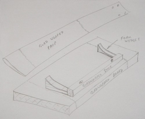 Press the trailing edge of the prop against the stick at the same time clamping the prop to the board and so compressing the foam wedges. Ensure there is still at least a 4mm gap between the prop and the board at the closest point and adjust clamps to give the desired blade angle. NOTE: this is blade angle at the Root and not the tip as normally referred to. From memory, I chose 8 degrees for the tip and the blade modification gave 4 degrees between the tip and the root. So that gave a blade angle at the root of 12 degrees. Now with the prop clamped at the correct angle, mount the board in a vice such that it is vertical with the prop leading edge horizontal. Mix resin and pour into the cavity adding chopped glass at an even consistency. Be careful not to poke a hole through the Glad wrap. Fill to just overflowing. When set, remove from mould. The Glad wrap is removed by light wire buffing on the grinder. Cut into 3 equal lengths. With a small clamp, secure each in turn to the root of a prop and drill holes for the clamping bolts. After several positioning tests, my final mounting used Sikaflex-291, an adhesive/sealant/bedding compound for a permanent secure mounting. was working fine... til the smoke got out. Cheers Gill _Cairns, FNQ |
||||
| feix62k Newbie Joined: 30/07/2008 Location: AustraliaPosts: 36 |
thanks mate the scetch is great it will give me all the incentive I need to finish my project .yes sikaflex is good gear my son uses it for everything once again thanks for the info really informative dont the days seem lank and long when nothing gos right and everthing gos wrong |
||||
| The Back Shed's forum code is written, and hosted, in Australia. | © JAQ Software 2026 |
