Notice. New forum software under development. It's going to miss a few functions and look a bit ugly for a while, but I'm working on it full time now as the old forum was too unstable. Couple days, all good. If you notice any issues, please contact me.
tomasp Newbie Joined: 20/10/2006 Location: New ZealandPosts: 28
Posted: 12:48pm 14 Apr 2007
Copy link to clipboard
Print this post
Hello everyone.
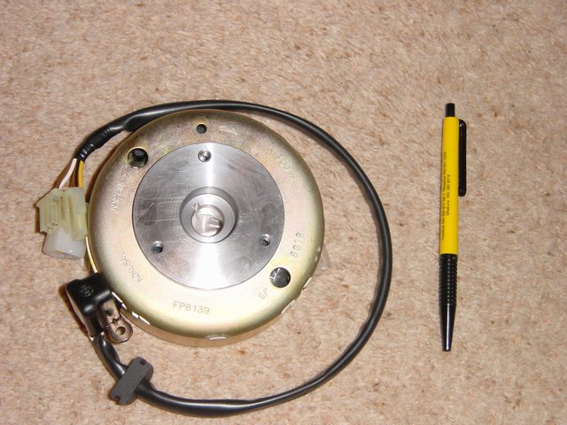
I have just acquired a nice magneto/alternator made by Kokusan in Japan. After some searching on the net found out that it is usually fitted in dirt bikes with CDI ignition. It is small but very solid and heavy (I'd say 2.5kg or so) - no plastic here, even the stator is all metal. Has 4 strong permanent magnets, 9 charging coils, 1 trigger coil, magnetic (RPM?) sensor and is very much like F&P motor (static stator and spinning rotor around it). Pictures follow below.
Now - the questions I have:
1. How can I tell the number of phases etc., I guess what I mean is I would like to understand what the output is over 1 revolution. A bit confused with number of magnets per number of coils etc..
2. I would probably rewind it to use it as a wind genny, throwing away the trigger coil and using its core and two other empty cores for coils. What sort of wire should I use (diameter) to get a decent output?
3. I know it is a bike magneto and probably not the ideal candidate for a wind application, but can it be used as one successfully (after rewind?). I am looking for up to 300W output in 5-10m/s winds.
According to some info I found on the Internet it should produce 14.5 - 17.5V at 200RPM as it is at the moment.
Sorry if some questions are dumb or basic and thank you very much in advance for your answers
Edited by tomasp 2007-04-15
Gill Senior Member Joined: 11/11/2006 Location: AustraliaPosts: 669
Posted: 04:04am 15 Apr 2007
Copy link to clipboard
Print this post
G'day Tomasp,
Could you check to see if the 4 magnets are in fact that or a magnetic block of several North South sections? was working fine... til the smoke got out.
Cheers Gill _Cairns, FNQ
tomasp Newbie Joined: 20/10/2006 Location: New ZealandPosts: 28
Posted: 10:02am 15 Apr 2007
Copy link to clipboard
Print this post
Hi Gill,
And thanks for the reply. You were right - I just checked with a little magnet and it looks like every block has 2 magnets in it. If you go around, it is N-S-N-S-N-S-N-S, total (4 blocks x 2 magnets each) of 8 alternating polarity magnets.
Cheers,
Tomas
Gill Senior Member Joined: 11/11/2006 Location: AustraliaPosts: 669
Posted: 11:21am 15 Apr 2007
Copy link to clipboard
Print this post
I'm thinking that what you've got there is 3 phase.
And I would be looking for a neutral point opposite to where the 3 yellow wires start as I expect it would be wired in Star configuration.
If you removed the windings of that black coil, and I'm guessing thats the brown and white wire, you could add an extra coil to the 3 already in series for each phase.
I would measure the wire gauge and extend with the same size. Now if it does output a nominal 16 volts @ 200rpm, then you could expect around 21volts at those same revs.
That would give a reasonable cut-in rpm.
Dirt bikes rev much higher than F&P smartdrives so I expect the wire is heavier than you need so can easily handle the extra coils.
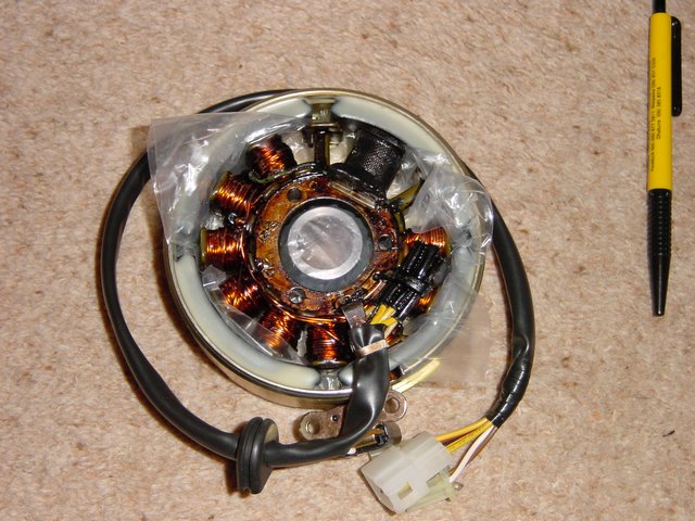
Expect cogging to be an issue though the magnets can't be that powerful considering the plastic bag wrapping to extract the stator from the hub. (second photo)
There are ways to duplicate the same number of turns for the added coils but the the basic way is to unwind the end coil counting the turns as you go.
There is no way of knowing expected power output. It's a case of suck it and see.
Well thats my best guess
Good Luck with the project.
was working fine... til the smoke got out.
Cheers Gill _Cairns, FNQ
tomasp Newbie Joined: 20/10/2006 Location: New ZealandPosts: 28
Posted: 12:12pm 15 Apr 2007
Copy link to clipboard
Print this post
Thanks, Gill. There is a point right opposite the 3 yellow wire sleeves where a few (looks like 2 - but maybe 3?) wires are twisted together. The problem is that whole stator is covered in blackish epoxy (?) and it is stone hard - is there a way to disassemble it somehow?
The wire looks 0.8 or 1mm diameter. Magnets are quite strong, it takes quite a lot of effort to pull the stator out of the rotor.
So if I add three more coils, how should I connect them to the existing ones?
Thanks again,
Tomas
Gill Senior Member Joined: 11/11/2006 Location: AustraliaPosts: 669
Posted: 01:21pm 15 Apr 2007
Copy link to clipboard
Print this post
Ok Tomas,
It was just to know what you were dealing with that we looked for the neutral point. It makes it easier to extend if thats the case.
The three yellow wires will have to be peeled back to expose the (solder?) connections to the winding wire.
One wire will come from each of the last three coils.
That is, one wire from the last coil, one wire from the second last coil, and one wire from the third last coil.
Warning: if the yellow wire connects to two winding wires, one coming from the coil and the other going back around to the start coils then we've got Delta. Get new instructions.
The third last gets (yellow cut off) extended and wound around the next empty pole the same number of turns. The middle to the middle(that black winding removed).
and the last winding extended to the last pole.
Reconnect yellow wires to each of the new coils and thats it. OK use a different colour if you want..
The hardest part is removing epoxy and unwrapping and counting turns on a coil. People(me) often count one more or less than they should. Why is that????? was working fine... til the smoke got out.
Cheers Gill _Cairns, FNQ
tomasp Newbie Joined: 20/10/2006 Location: New ZealandPosts: 28
Posted: 07:58am 16 Apr 2007
Copy link to clipboard
Print this post
Thanks for your input, Gill, I really appreciate it. I have saved your instructions and will be thinking now about removing that epoxy. Is there an "easier" way to do that or not? Any chemicals?
KiwiJohn Guru Joined: 01/12/2005 Location: New ZealandPosts: 691
Posted: 08:37am 16 Apr 2007
Copy link to clipboard
Print this post
G'day Tomasp,
I dont see any need to unwind any coils, just get some wire of same gauge and carefully wind another coil until it is as near as you can judge the same size as the existing coils. Count your turns and you can wind the other two to the same size. I cant imagine that there is any problem with one coil having a few more or less turns than those it is connected with.
I think acetone softens epoxy but I would try to avoid the use of solvents as anything that can strip the epoxy might also strip the insulation and cause short circuits in the coils..
tomasp Newbie Joined: 20/10/2006 Location: New ZealandPosts: 28
Posted: 08:47am 16 Apr 2007
Copy link to clipboard
Print this post
That is interesting, KiwiJohn! So it's not really a problem if one (or more) coils have a bit more/less turns?
Going a bit further - what if I decide to rewind the whole lot, how can I calculate coil parameters needed? Are there any good resources on the net for that (easy to read) so that I can stop bugging everyone here :) Cheers
KiwiJohn Guru Joined: 01/12/2005 Location: New ZealandPosts: 691
Posted: 07:04am 17 Apr 2007
Copy link to clipboard
Print this post
G'day Tomasp,
I am certain that coil parameters could be calculated but it would be way beyond my capabilities and I doubt anyone could do it without some measurements of stuff like magnetic flux, permiability etc.
As a general rule though, more turns mean more volts but more turns require thinner wire to fit in the space available. So you end up with more volts, less amps but watts are about the same. If the volts are about right for your application then I dont see any useful prospect in fiddling around with different coil sizes. Maybe someone will have an other opinion.
Yep, a few more turns would just mean that that particular coil had a bit more voltage than the others but as all coils in the phase are in series they dont have to be balanced in any way though it would be nice to have equal phases and thats why I suggest winding your new coils to be all the same.
WindChopper Newbie Joined: 08/02/2007 Location: United StatesPosts: 15
Posted: 10:35am 17 Apr 2007
Copy link to clipboard
Print this post
Like KiwiJohn said .... make the additional series coils the same and it should get the job done for you.
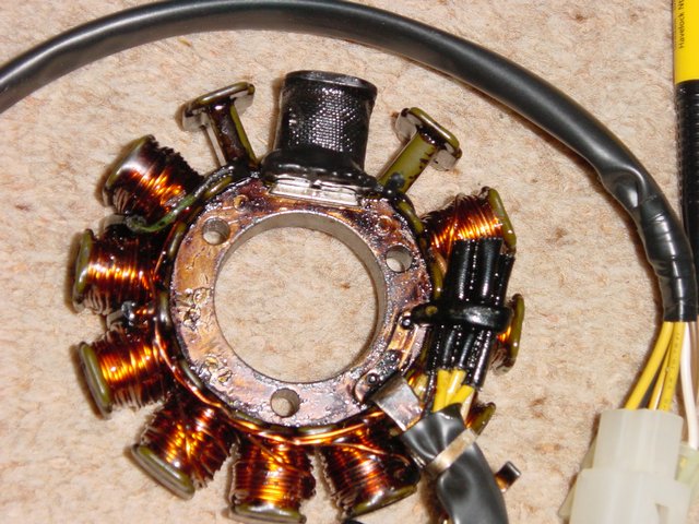
I tried to scale a guestimate from your third picture .... looks like maybe 3 tight wound layers at 15 to 16 turns per layer plus some scramble wound on a 4th layer (?) .... 50-60 turns (?) .... a trial coil will answer that fast !
Take a look at .... http://www.kokusandenki.co.jp/english/index.htm .... yours is #3 ( FP8139 ) .... you might try an e-mail to them at eig@kokusandenki.co.jp listed on their contact page.
Then take a look at #10 ( GP9416 ) .... 380w at 14V .... the Japanese F&P?
Looks like you have the start of a nice mill - have fun!
Russ
IE7 just crashed on me ( again ) so hope that this does not get double posted.Edited by WindChopper 2007-04-18
tomasp Newbie Joined: 20/10/2006 Location: New ZealandPosts: 28
Posted: 11:08am 17 Apr 2007
Copy link to clipboard
Print this post
Hehe - nice, huh? That number 10 looks yummy, I have indeed asked for more info from them. What I really like about the one I have is that it is SO SOLID, I mean you should see how thick the steel of the rotor is. Everything is made to last. I also have to figure out the shaft, it should be coned and has a notch in it.
One more thing - I sort of understand the theory behind the number of coils and phases etc, but what do you do with the number of magnets, I mean what does it tell you?Edited by tomasp 2007-04-18