
|
|
Forum Index : Windmills : VAWT and F&P recomendations
| Page 1 of 4 |
|||||
| Author | Message | ||||
Robert_VK2BBR Regular Member Joined: 31/12/2006 Location: AustraliaPosts: 67 |
Hi all, I am thinking of building a VAWT, so seeking collective wisdom/experience. What has proved sucessfull on a F&P? cheers Robert 1555 W grid connect system since Jan 08 both vehicles running on modified, used vege oil. |
||||
| Robb Senior Member Joined: 01/08/2007 Location: AustraliaPosts: 221 |
What levels of wind do you expect to use it in? |
||||
| Robert_VK2BBR Regular Member Joined: 31/12/2006 Location: AustraliaPosts: 67 |
Robb, I had hoped a low wind speed, even if i had to gear it up to drive the F&P. cheers Robert 1555 W grid connect system since Jan 08 both vehicles running on modified, used vege oil. |
||||
| Gizmo Admin Group Joined: 05/06/2004 Location: AustraliaPosts: 5182 |
I used a 3 wing Lenz2 windmill to directly drive a F&P. It was only a small windmill, 1.2 meters high by 1.3 wide. It made 1 to 2 amps most of the day in light winds, sometimes going over 3 amps when the winds picked up. To make it work better, I wanted to double its height to 2.4 meters and this should have given a good power increase. But the project was put on hold for now. Glenn The best time to plant a tree was twenty years ago, the second best time is right now. JAQ |
||||
martinjsto Senior Member Joined: 09/10/2007 Location: AustraliaPosts: 149 |
hi guys, we get hot weather here in australia and use wirlybirds(a type of roof venting system) to remove heat from roofs, theroretically you should be able to assist a V.A.W.T quite a bit, even get power from still days just from updraught, the wirlybirds spin realy fast but are only about 400mm diameter so not sure of the torque. i have seen systems on the net mounted to sides of multystory buildings in cities and close housing estates, the updraugh around there is huge and these systems seem to work continuosly. its the torque we need, once these generaters are loaded they can stall quickly, i think you need a large diameter rotor to ensure good torque and i was also thinking of a flywheel of some kind so when the unit got up to speed it tended to keep going. its getting up to speed thats the trick, i was also thinking about a centrifugal switch that enguages the power at a certain rpm ensuring good suply of power, whats your thoughts? anyone know of a centrifugal swithching mechanism pls let me know. martinjsto free power for all McAlinden WA |
||||
| Larry Newbie Joined: 08/12/2007 Location: Posts: 2 |
I am working on this principle... 5 feet tall, 2 feet diameter... wind deflectors to minimize drag and maximize pull... geared 6:1 on a treadmill motor... I will be done in the spring... good luck... 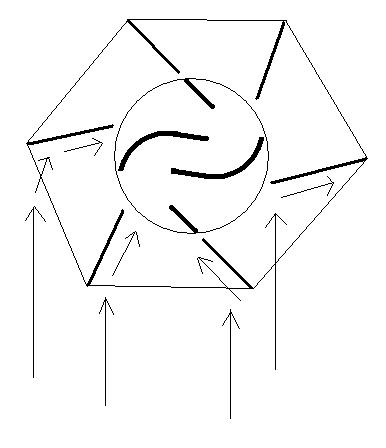
Lar. |
||||
Gill Senior Member Joined: 11/11/2006 Location: AustraliaPosts: 669 |
G'day Larry, I see what you are trying to do and like your inventiveness, however feel that your design may not work as well as you hope for the following: You have increased the capture area by adding vanes to intensify the power to a smaller central savonious. you seem to understand it is the more efficient profile hence the heart of the design. Perhaps with some further consideration you will see that a savonious of the same size as your total size would therefor be more efficient than a boosted smaller one. Both have the same wind capture area. For a more even torque, stack a second savonious on top of the first but offset by 90deg. (Two @ 2ft 6in high.) Your dimensions reflect a design style popular with some Poms at the moment, however the more efficient savonious are the opposite, ie. short and fat not tall and thin. I understand this design is convenient for use of PVC piping however performance is abysmal considering it's capture area. I don't mean to deter you from making your design, just make you aware of it's design characteristics. was working fine... til the smoke got out. Cheers Gill _Cairns, FNQ |
||||
| martinjsto Senior Member Joined: 09/10/2007 Location: AustraliaPosts: 149 |
i have seen a system that uses a scroll as the savoniouse, there are numerouse blades set about 200mm apart on the outer circumference of the rotor, these can be varying in lengh see http://images.google.com.au/imgres?imgurl=http://ecoenergysu pplies.com/images/gse_diag.gif&imgrefurl=http://ecoenergysup plies.com/vawt.html&h=195&w=200&sz=6&hl=en&start=151&um=1&tb nid=kCijg2a8F-hD_M:&tbnh=101&tbnw=104&prev=/images%3Fq%3Dvaw t%26start%3D144%26ndsp%3D18%26svnum%3D10%26um%3D1%26hl%3Den% 26sa%3DN 
the longer you make the blades the more torque i believe gill do you think the same, that the booster used here wont gain compared to one of total size? martin free power for all McAlinden WA |
||||
| Gill Senior Member Joined: 11/11/2006 Location: AustraliaPosts: 669 |
martinjsto, What you are doing by increasing the height(length) is increasing the torque but only by the fact that you have increased the capture area. This tall height is primarily to make up for lack of torque because it is designed for higher speed. So basically a short fat savonious will have higher torque and slower speed and a tall slim savonious will have higher speed but lower torque for the same capture area. I'm calculate that by adding the fixed vanes they increase the capture area but maintain the high speed turbine profile. Very clever! Be aware that these vawts are aerodynamically designed, your sketch was not. Their turbine has multiple blades also aerodynamically profiled, your sketch showed a simple savonious. Whilst I now see what they have done, I would be cautious of just slapping something together that looked close. Still a very interesting project if you're prepared to get into the figures. Good luck with it. was working fine... til the smoke got out. Cheers Gill _Cairns, FNQ |
||||
| martinjsto Senior Member Joined: 09/10/2007 Location: AustraliaPosts: 149 |
thanks gill i also found this info from outpower similar design and the fellow reccons 3 times the speed whats yout thoughts? http://www.fieldlines.com/story/2007/12/12/9444/1180 free power for all McAlinden WA |
||||
| Gill Senior Member Joined: 11/11/2006 Location: AustraliaPosts: 669 |
G'day Martin, Firstly, be aware that I have never built a vawt so all my comments are opinion only. It would be better if you could get comment from someone backed by practical experience. {Vawtman your que} I've browsed the link you've posted. Very interesting read. There are 2 things that stand out in that thread. Firstly, no generator was attached. Secondly it was all speculation from both the for and against. So to get involved in a similar project you would be starting an experiment and not building a proven performer. The arguments of HAWTS v VAWTS are similar to MAN v WOMAN, for entertainment value only. From the pic I could not see an increase of 3 times as possible all things being equal. Yet there may well be increases that warrant further looking in to. I like the idea of an increased capture area being applied to a reduced swept area. Unfortunately the sheer bulk of the design poses limits to many applications. I think many working examples will need to be made and reported on before one could tackle building one with confidence. So when are you making a start on yours? was working fine... til the smoke got out. Cheers Gill _Cairns, FNQ |
||||
Megawatt Man Senior Member Joined: 03/05/2006 Location: AustraliaPosts: 119 |
Hello Gentlemen, Look at this link, its been mentioned on this site before. http://www.gual-industrie.com/Doctechang.pdf This one impresses me. One of the problems with VAWTs is that they have a tip speed ratio of less than one, ie the velocity of the outer surface of the rotor is less than the velocity of the wind through it, unlike the HAWT. When you channel the wind through, as with the device on this link, you use the Bernoulli effect and that increases the velocity of the air flow through the blades, so you increase the TSR with consequent increases in output etc. The arrangement really does look like that you see on gas and steam turbines. I would reckon that very much theoretical thought, capped off by very much experimental work has gone into the creation of these machines. I would guess that we couldn't just scale off the shape and dimensions from their pictures, because they would have wanted to protect their IP, so maybe they would have changed the vertical/horizontal ratios before publishing the pics. But I reckon its the way to go. They can be on the roof, or on an exposed hilltop at ground level. They can't fall over the fence. But I reckon if you had one on the ground, you'd need a mesh fence around it smaller than your dog. Incidentally the TSR limitation is because the back of the blade must push its way through the oncoming wind before it rotates to a position where it becomes the driven blade. When you use incoming guides, you can arrange them so they shield the back of the blades on their return journey. The Chinese found that out some 2,000 years ago with their bamboo VAWTs that they used fir irrigation, they built mud brick walls to guide the wind in and protect the rear surfaces of the blades. Of course the walls had to be on the side from which the prevailing winds blew. So what we need is an experienced fluid flow person to do some numbers on the concept and tell us what shape the rtotor blades and the guide vanes need to be. I don't know whether the other link posted was for the Russian VAWT that was posted maybe a year ago. It was of relatively small diameter and large height and it sounded like an air raid siren while operating. That won't happen with the larger units, because of lower rotational speed at least. Megawatt Man |
||||
| Gill Senior Member Joined: 11/11/2006 Location: AustraliaPosts: 669 |
I am of the opinion that for a VAWT to be successful it has to harness the wind from most all of it's swept area. If it fails to generate torque on it's approach to wind it is merely a drag machine. The example I would liken it to is a sailing yacht. What degree can the America's Cup challengers sail into the wind? Is it not something like 5deg?? With a 360deg change in relative wind direction to the turbine blade, I feel that like a yacht's change in sail profile to suck out the power, a VAWT needs to change each blades profile as it changes angle to the wind too. Hence my inclination to a flexible blade skin. But I dream to much. The used of deflection vanes to make the wind change to suit a fixed blade's current angle must reduce the available power. If it sacrifices some power to apply it to a smaller swept area for the purpose of higher revs, well and good. But I can't see where vanes can increase power over a turbine of equal capture area, and certainly not 3 times the power. Perhaps on a poorly designed drag machine. One thing for sure, designing a new successful VAWT won't be easy. was working fine... til the smoke got out. Cheers Gill _Cairns, FNQ |
||||
| Gizmo Admin Group Joined: 05/06/2004 Location: AustraliaPosts: 5182 |
I've built a few VAWT's and HAWT's over the last couple of years. The VAWT's have been mostly drag type machines, the biggest was a Lenz2 on a F&P at 1.2 meters high and 1.3 wide. It worked, made 20 to 40 watts. I really needed to double its height to say it was a successfull windmill, be never got round to it. What I find is HAWT's are much easier to make, lighter and need less materials. In my local clean summer winds they work great. In my turbulent winter winds, I found my Lenz2 windmill worked better. I think its a matter of location. Honestly, if a VAWT needs a tail to find the wind direction, then it would be cheaper and easier to build a HAWT, other than the fun factor of building something different of course. The big advantage of a VAWT is it can take wind gusts from any direction and instantly turn that into power, where a HAWT needs to find the wind. I think there is a place for both machines, I like VAWT's, but have always been limited to making small one's due to the extra materials and complexity of the design. I found the little Miller rotor I made worked great, and would like to scale it up, but when I worked out the cost of sheeting those big wings, I gave it a miss and went back to working on the HAWT windmill. Glenn The best time to plant a tree was twenty years ago, the second best time is right now. JAQ |
||||
| martinjsto Senior Member Joined: 09/10/2007 Location: AustraliaPosts: 149 |
thanks for the info, megawhatman, gizmo and gill. that pdf looks like the same image i was tring to show in my first post, it looks like the hawt has less turbulent issues but not needing to follow the wind is a great advantage for the vawt. hmm... puting a tail on it wont help, the only way is to protect the other side from the wind or possably incorparating a vain that will twist to be parralell with the oncoming wind and open up to capture the wind, any think added will surely increase its inertia though.i thought of a folding blade like a folding piece of paper, once facing the wind it will blow open but once 180 degreea around it will close up i am going to start a unit in the new year, a series of centraly hinged blades opening to capture the wind and closing to bypass the incoming drag. 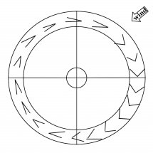
martin free power for all McAlinden WA |
||||
| Megawatt Man Senior Member Joined: 03/05/2006 Location: AustraliaPosts: 119 |
G'day martinjsto, Another thought is to use a shield of aluminium that covers one half of the outer circumference. It would be mounted on a track or the like,so it rotates with wind direction driven by a vane so it keeps the backs of the rotor blades shielded from the incoming wind. There might be less mechanical work with that than arranging for moving blades. It does however do away with one of the claimed advantages of the European turbine to which I have posted the link and that is, instant response to changes in wind direction. Compromise, compromise. If you look at the arithmetic of the European setup, you'll see that the stator has a diameter of 4000 while the rotor would be about 3000. Thus, wind from an area that is proportional to 4 is being directed into the rotor that has an area proportional to 3. That is why such a VAWT can claim TSRs greater than unity. Megawatt Man |
||||
vawtman Senior Member Joined: 14/09/2006 Location: United StatesPosts: 146 |
The wind will take the path of least resistance.So if you have a structure to force and speed up the flow my opinion is you will get a glancing blow. Any sheilded turbine will still suffer from drag on the rotation. Anything with adjustable flaps would not be good either.Been there done that. Let the wind blow through and gather what you can.My motto |
||||
| Gizmo Admin Group Joined: 05/06/2004 Location: AustraliaPosts: 5182 |
Yeah I agree with vawtman, let the wind blow through your turbine and make use of it where you can. Have a look at the Ropatec design and Lenz2. The Ropatec is a lift based windmill, like a darrius but not as fast. The lift verticals make use of the wind through over 300 degrees of rotation, so even when the blades starts to head up wind its making power. The Lenz uses a combination of lift and drag to give the most power just under 1 tsr. Glenn The best time to plant a tree was twenty years ago, the second best time is right now. JAQ |
||||
| KiwiJohn Guru Joined: 01/12/2005 Location: New ZealandPosts: 691 |
Can anyone advise which is the style of VAWT for areas with long periods of light to moderate winds and occasional extreme winds, 100 knots is not unknown around here! (Yes, I meant knots not kmph) |
||||
| Gill Senior Member Joined: 11/11/2006 Location: AustraliaPosts: 669 |
This is my idea of changing profile. Applied to Glenn's early HAWT 
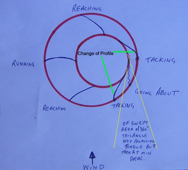
Edit: Ooops! topmost sail/vane is back-to-front. If you've ever done any sailing you'll immediately understand the terms and aerodynamic profiles. In basic theory this should produce torque for most of the 360deg. In reality there are considerations of relative wind flow as well as changing flow through the turbine itself. Still I feel a turbine with an adaptive flexible profile such as this will cope with these without the need for the DIY experimenter to have a degree in aerodynamics and a wind tunnel. And before you say it, I agree, All those working parts are a minus. But any comments on the principal idea? was working fine... til the smoke got out. Cheers Gill _Cairns, FNQ |
||||
| Page 1 of 4 |
|||||
| The Back Shed's forum code is written, and hosted, in Australia. | © JAQ Software 2026 |
