Home
JAQForum Ver 24.01
Log In or Join  
Active Topics
Local Time 19:28 16 Jul 2025 Privacy Policy
Jump to

Notice. New forum software under development. It's going to miss a few functions and look a bit ugly for a while, but I'm working on it full time now as the old forum was too unstable. Couple days, all good. If you notice any issues, please contact me.

Forum Index : Windmills : Really easy to make hub for F &Ps.

Author Message
KiwiJohn
Guru

Joined: 01/12/2005
Location: New Zealand
Posts: 691
Posted: 09:55am 10 Dec 2005
Copy link to clipboard 
Print this post

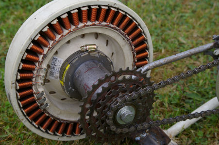
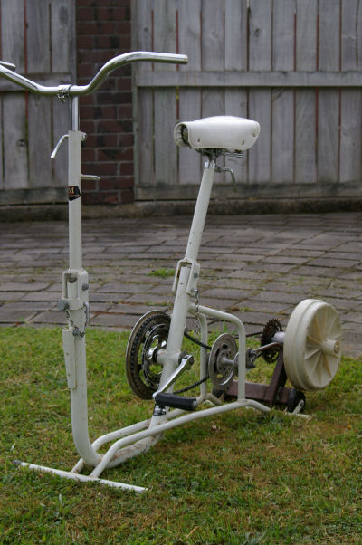
Working on my pedal generator I had to  make a hub to hold the two bearings and support the stator accurately centred inside the rotor.

I dont have a lathe or much in the way of machine tools so I had to put the gray matter to work!

This is what I did,  I found a length of two inch internal diameter water pipe and cut off a piece shorter than the F&P shaft being careful to get the ends as square as possible.

Quite a long time with a drill and emery flap wheel opened the ends enough for me to be able to press the bearing in. 


 In hindsight I could have just slotted the ends with a hacksaw, pressed the bearings in then welded up the hacksaw cuts,  not truely accurate but good enough for the two knackered bearing I have to put in.


So I had two bearings and a piece of pipe they would fit in. There was a ridge on my shaft so I ground that off as neatly as I could.

I put the rotor on the shaft and placed the rotor on a level surface with the shaft vertical above it.  I used the original plastic nut to mount the rotor as I have been told it is very difficult to get the rotor off the shaft without this very hand nut.

I used tape to close the four mounting holes in the stator putting the tape on the outside and also put tape around the ring of plastic tabs that are on the other side of the stator. 

Then I dropped the stator over the shaft and into the rotor.  I cut strips of plastic from a plastic carton and put these all around between the coils and the magnets.  It was quite a struggle to get the last few in but when I was finished the stator was being held centrallised inside the rotor.

One bearing I slid over the shaft and used just a little mastic to seal the edge of bearing to the centre of the stator.  Next I dropped my piece of water pipe over the shaft and around the bearing.  The second bearing got put on from the top and tapped down into the end of the water pipe.

I mixed up enough polyester resin to fill the space between the water pipe and the ring of plastic tabs.  Most of the resin stayed in and there was only a little leak in one of the stator mounting holes.  I should have fluffed up some glass fibres and put them in the resin but none was on hand, next time I will be prepared.

When the resin set (overnight) I pulled the bits of plastic from around the magnets and was very pleased to see that the rotor turned without catching anywhere.  The nut made it easy to draw off the rotor and pick out the little dribble of errant resin, I removed the bits of tape at the same time then put the rotor back on but not screwed quite as far to ensure clearance with the stator.

There was only one last bit to do and that was to fit a large hose clip of the screw tighten type around the ring of plastic tabs as there is very little binding to the solid resin piece.

I can take the rotor off by unscrewing its plastic nut and then by releasing the hose clip the stator comes away easily too.

This seems to be plenty strong enough for the job and the water pipe is plenty heavy enough to weld your support to plus I think it gives adequately rugged support for your propeller hub.

I hope this idea is useful to someone!


Chris

Senior Member

Joined: 12/09/2005
Location: Australia
Posts: 146
Posted: 10:04am 10 Dec 2005
Copy link to clipboard 
Print this post

Wow, thats a pretty good idea! From what i understood, sorry its a bit hard to picture it all in my head! But some photos would help if you could get some of the process.

From what i understood you made the bearing retainer plate (the part that glenn usually laser cuts out of steel) out of a polyester resin mold? Its a great idea, I have some fibreglass resin laying around, im going to try it on my mine one day.

Did you make it so you can remove the mold? Or isnt that necessary, probably isnt ey? as long as you can get the bearing out thats fine i guess.

Great idea,
Thanks

Edit: I read it a second time and it made perfect sense. Thanks!
Edited by Chris 2005-12-11
 
KiwiJohn
Guru

Joined: 01/12/2005
Location: New Zealand
Posts: 691
Posted: 10:37am 10 Dec 2005
Copy link to clipboard 
Print this post

Chris, there is no mold,  you basically assemble the whole thing then pour resin in the space between the end of the pipe and the ring of plastic tabs on the stator.

The resin does not stick to the F&P bits so everything comes apart easily, too easily in fact, so thats where the hose clip comes into play.

 
Chris

Senior Member

Joined: 12/09/2005
Location: Australia
Posts: 146
Posted: 03:36am 11 Dec 2005
Copy link to clipboard 
Print this post

Why doesnt the resin stick to the F&P bits?
 
KiwiJohn
Guru

Joined: 01/12/2005
Location: New Zealand
Posts: 691
Posted: 04:49am 11 Dec 2005
Copy link to clipboard 
Print this post

I am not sure why it does not stick to the F&P bits but I assume it is because of the really smooth plastic surface.  It think it is good that it does not stick as with only a strong hand to undo the rotor nut and a screw driver to release the hose clip I can change the F&P components in just a couple of minutes.
 
Chris

Senior Member

Joined: 12/09/2005
Location: Australia
Posts: 146
Posted: 10:08am 11 Dec 2005
Copy link to clipboard 
Print this post

I guess your right that its good, how thick are the drainpipe walls you use?
 
KiwiJohn
Guru

Joined: 01/12/2005
Location: New Zealand
Posts: 691
Posted: 06:12pm 11 Dec 2005
Copy link to clipboard 
Print this post

Chris, it is heavy well galvanised pipe, I guess about 3 or 4 mm wall thickness.

I am sure it does not have to be that heavy and I had originally thought of using exhaust tube until I found this bit lying under the house, as one does! 


KiwiJohn
Guru

Joined: 01/12/2005
Location: New Zealand
Posts: 691
Posted: 08:39am 18 Dec 2005
Copy link to clipboard 
Print this post

My poured resin hub in the pedal generator!


Here is the complete machine!


Notice the two stage gearing,  I have since gone to a single stage configuration which means the F&P now spins at about 250 rpm when pedalling at an easy 85 rpm.    Available output at not-too-exhausting pedalling rate is about 90 watts.

Edited by KiwiJohn 2005-12-19
 
feix62k

Newbie

Joined: 30/07/2008
Location: Australia
Posts: 36
Posted: 08:57am 05 Nov 2008
Copy link to clipboard 
Print this post

hay I like the peddle bike what electrics did you use phases rectifier ect thanks Shane
dont the days seem lank and long when nothing gos right and everthing gos wrong
 
Print this page


To reply to this topic, you need to log in.

The Back Shed's forum code is written, and hosted, in Australia.
© JAQ Software 2025