
|
|
Forum Index : Windmills : 2 Speed F&P Turbine
| Page 1 of 2 |
|||||
| Author | Message | ||||
jamarc Newbie Joined: 27/10/2007 Location: New ZealandPosts: 10 |
On the electrical page of the Fisher & Paykel Mill kit http://www.thebackshed.com/Windmill/assembly6.asp it talks about a circuit that switches the windings from Star to Delta as the RPM increases. This would improve the efficiency of the turbine across a wider wind range, effectively giving it a second gear. Has anyone played with this and have a circuit diagram for it?  |
||||
BUGS Newbie Joined: 12/04/2007 Location: AustraliaPosts: 21 |
I found this site a few years ago,star/delta switch. http://www.dsgnspec.com/StarDelta.html BUGS |
||||
| jamarc Newbie Joined: 27/10/2007 Location: New ZealandPosts: 10 |
Thanks Bugs, I'll check it out. |
||||
| vasi Guru Joined: 23/03/2007 Location: RomaniaPosts: 1697 |
Yes, but you don't have the software! So, maybe we can do one here .Hobbit name: Togo Toadfoot of Frogmorton Elvish name: Mablung Miriel Beyound Arduino Lang |
||||
| GWatPE Senior Member Joined: 01/09/2006 Location: AustraliaPosts: 2127 |
Before any program is written we need some parameters. Obviously there will be some major loading effects that will change the output. Should use output amps as the switching control input. There will need to be some timing delays so the relays don't chatter at the changeover point.[ this is because we need break before make relays and there will be a moment when no current flows during the changeover.] Picaxe 08M could be used. This would allow software calibration. If 4V main picaxe supply rail used, then 4mV per ADconverter step is achievable. If we concede 100mV at 5A for the shunt sensor, then we get 25 step count at the changeover point. The output Voltage will fall by a factor of 1.7 approx, going from star to delta and the current will increase by that amount at the same rpm. There may be a current lull as the mill responds to the sudden unloading in the star to delta transition and a current surge on delta to star. There will need to be some individual software tuning to get a somewhat smoothed transition. I am sure this will be do-able. The type of relay will be important. All relays will be of double throw type. I think 6 relays are needed. All need to be de-energized in the star position. here is some example code that could be used for control with picaxe 08M ' conditions are ' generator current > 6 amps then switch ON, on way up. ' generator current < 4 amps then switch OFF on way down ' pin 6, ADC1 is unused ' pin 5, ADC2 is Mosfet control output ' pin 3, ADC4 is shunt sense voltage ' pin 4, IN3 is unused ' pin 7, OUT0 is unused Symbol Svolts = W0 Symbol relayONvoltage = W1 Symbol relayOFFvoltage = W2 Symbol delayONset = b6 Symbol delayOFFset = b8 Symbol timing = b10 Symbol counter = b12 svolts=0 DelayONset=0 DelayOFFset=0 counter=0 low 2 ' ------------------------------------------------- ' change this value to tune the delay time timing = 50 ' -------------------------------------------------- ' adjust these values to set relay operating points relayONvoltage=30 relayOFFvoltage=20 ' ================================================== Main: readadc10 4, SVolts if SVolts > relayONvoltage and delayONset=0 then gosub UPCounter if SVolts < relayOFFvoltage and delayOFFset=0 then gosub DownCounter goto main ' =================================================== UPCounter: high 2 delayONset=1 delayOFFset=0 for counter=1 to 100 pause timing next return DownCounter: low 2 delayOFFset=1 delayONset=0 for counter=1 to 30 pause timing next return I have been very generous with variable use so it will be easy for others to modify the code to suit needs. The cct would be cheap too. Works on simulator. If a logic level FET is used then cct is simple. Other readers will have views in wiring of relays etc. The only down side is that all has to be on the mill head and weather protected. including rectifiers. This would be powered from the battery and switches ahead of the rectifiers. I hope everyone understands all of this. cheers, Gordon. become more energy aware |
||||
| KiwiJohn Guru Joined: 01/12/2005 Location: New ZealandPosts: 691 |
Headlamp dip relays might be useful for this? Hmmm... the requirement is to close the relays at 6 amps and open them when the current drops below 4 amps? I dont think any electronics are needed to do this, just pull the coil out of a relay and rewind with a few turns of heavy copper wire, 0.8mm or such like. Put on enough turns so that 6 amps is enough to close the relay. Once closed the relay will tend to stay closed way below the current that caused it to close. These are the relay 'closing' and 'holding' values. Open the magnetic gap if the closing and holding values are too close together. Use this one relay to control the 6 relays that actually do the work. |
||||
| GWatPE Senior Member Joined: 01/09/2006 Location: AustraliaPosts: 2127 |
Hi KiwiJohn, I think the rewinding of a relay may work, but I am over winding coils. I hand wound the stator in my mill. 44 coils and no laminations to hold them. A long story. I am not sure how you control the timing. The hysterysis of the iron core only gives one part of the solution. Some sort of on and off delays are still required. I have to say that the software solution does both. I am surprised that there has been no action on this before. Maybe no one had worked out the nitty gritty. Well, if readers want a cct, I will try and post one. Not much to it as all the hard work is in the chip. cheers, Gordon. become more energy aware |
||||
| GWatPE Senior Member Joined: 01/09/2006 Location: AustraliaPosts: 2127 |
Have just read the above link and only 3 SPDT relays needed. thanks to http://www.dsgnspec.com/StarDelta.html The cct I am proposing will measure probably 25mm x 25mm. Anyone handy with a soldering iron should be able to breadboard it. cheers, Gordon. become more energy aware |
||||
| vasi Guru Joined: 23/03/2007 Location: RomaniaPosts: 1697 |
Hi Gordon, The work was started by Ed from windstuffnow on this page http://www.windstuffnow.com/main/alt_from_scratch.htm [quote=Ed]................ This seems to be the best I've come up with so far so I decided to go with it ... unless someone comes up with something better... remember it must be simple! Below is a diagram of how the relay would be wired .................. [/quote] Then, the guy from dsgnspec.com come up with his controller .... Cheers, Vasi Hobbit name: Togo Toadfoot of Frogmorton Elvish name: Mablung Miriel Beyound Arduino Lang |
||||
| KiwiJohn Guru Joined: 01/12/2005 Location: New ZealandPosts: 691 |
Hi Gordon, I am primarily a software man myself but I am also a firm believer in the KISS principle. Maybe I will spend a little while finding just what would be required to make a relay that would close with 6 amps, not very much I expect and likely just a few turns of heavy gauge wire. Of course it does need to be heavy gauge as it will carry the output of the mill. |
||||
herbnz Senior Member Joined: 18/02/2007 Location: New ZealandPosts: 258 |
Quick response Use independant instead delta same thing Then you can get star two contacts shorting out one AC side bridge better tho to disconnect then short for star needs three change over contacts Herb I ll try upload image sketch ??????? No can do image to large my camera will try find time later to reduce 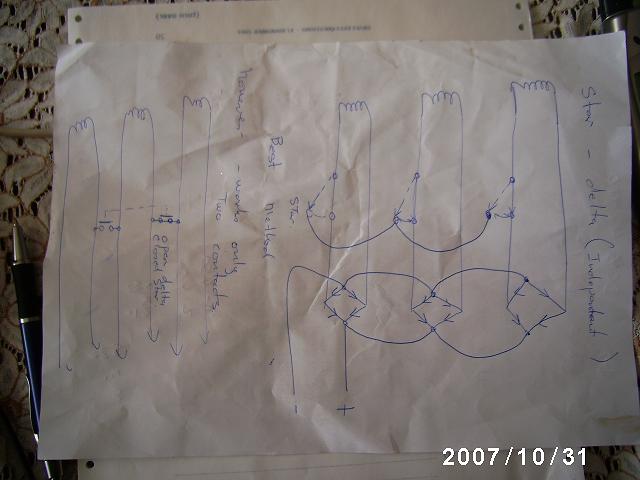
Sorry mistake in two contact version should short out one end leg each winding |
||||
| GWatPE Senior Member Joined: 01/09/2006 Location: AustraliaPosts: 2127 |
Hi all, Good Work HerbNZ. The above paper sketch, rectifying separate coils is what I do. I have 4 phases though. I have looked at the links provided. The external wiring of the coils is not the issue. Relay contacts will do fine. In http://www.windstuffnow.com/main/alt_from_scratch.htm This generator has a high internal wiring resistance, a large air gap, an iron core and thick wire directly in the changing magnetic field.[ You know how the magnetic resistance works on an exercise bike ]. My research, when I built my generator showed the cross section of the wire works the same way during magnetic flux transitions. I however commend people for getting out and building, as I have been there as well. The combination of these factors reduce the overall efficiency. The magnetic [cogging] binding at low rpm is however, low. Back to the point. On a F&P mill there will be a dead band in output at the crossover in the star to delta transition. Any relay drive solution has to provide the energy during this transition to keep the relay on as the mill rpm increases. The current may be zero until the rpm picks up and the mill puts out power in delta. The relay, if driven directly will cut out again when the current falls. Any timing will have to be low impedance and store enough energy to keep the relay on for this time. There should be different timing periods for the ON transition to the OFF transition. The software solution is not complex as the code is provided. I have done SMD artwork and it measures 20mm x 30mm. If readers wish to breadboard this then note that the picaxe must be grounded to the mill negative and the shunt is sensed on the battery negative. Picaxe only measures positive voltage from chip ground. use a logic level N-fet to drive the relay coil. Protect the fet with a diode across the relay coil. For best sensitivity use a 4V rail, 3V9 zener OK, with 3k3 resistor from 24V battery. picaxe cct needs minimal power. < 10 mA. This approach is simpler than rewinding a relay. I assume most readers are familiar with a picaxe and have resources to program. I have no test F&P mill yet, so I will not build a cct. I may provide a schematic and layout if sufficient readers would find it useful. I think most readers would have resources to do their own though. cheers for now, Gordon. become more energy aware |
||||
| jamarc Newbie Joined: 27/10/2007 Location: New ZealandPosts: 10 |
Hi GWatPE a schematic and layout would be very helpful cheers Mark |
||||
| GWatPE Senior Member Joined: 01/09/2006 Location: AustraliaPosts: 2127 |
Hi jamark, not enough interest yet. cheers, Gordon. become more energy aware |
||||
| commanda Newbie Joined: 12/11/2007 Location: AustraliaPosts: 14 |
If you use am LM2917 to make a tacho circuit, you can pull a dc voltage off pin 5 which is proportional to rpm. You can then feed this voltage to a comparator to switch a fet to operate the relays. You need a decent RC time constant between the LM2917 and the comparator, and also hysteresis. With a 4093, a switch, some diodes and leds, you can also have manual over-ride, and make the leds flash when in manual mode. I have built this. Actually the board also has an ammeter and an expanded scale voltmeter on it as well. Don't yet have a flying mill to live test it with. Let me know if you want me to upload the circuits here as well. Amanda |
||||
| jamarc Newbie Joined: 27/10/2007 Location: New ZealandPosts: 10 |
Thanks Amanda, Sounds like a great idea. Would like to see the circuits if you can. cheers Mark |
||||
| commanda Newbie Joined: 12/11/2007 Location: AustraliaPosts: 14 |
Here's a collection of circuits. I've built all of these. Be aware the dump load controller uses a 5 volt regulator, not 12 as shown on the circuit. There's more details, plus photos, etc, in my diary over on FL. Amanda 2007-11-19_195207_circuits.zip |
||||
| jamarc Newbie Joined: 27/10/2007 Location: New ZealandPosts: 10 |
thanks Amanda excuse my ignorance but I would like to check out your "more details, plus photos, etc, in my diary over on FL" . Where exactly would I find FL? Kind regards Mark |
||||
Bryan1 Guru Joined: 22/02/2006 Location: AustraliaPosts: 2101 |
Hiya Mark, Here is a direct link to Amanda's files on FL. Amanda's files Cheers Bryan |
||||
| jamarc Newbie Joined: 27/10/2007 Location: New ZealandPosts: 10 |
thanks |
||||
| Page 1 of 2 |
|||||
| The Back Shed's forum code is written, and hosted, in Australia. | © JAQ Software 2026 |
