Notice. New forum software under development. It's going to miss a few functions and look a bit ugly for a while, but I'm working on it full time now as the old forum was too unstable. Couple days, all good. If you notice any issues, please contact me.
Gill Senior Member Joined: 11/11/2006 Location: AustraliaPosts: 669
Posted: 01:29am 09 Dec 2007
Copy link to clipboard
Print this post
Hello Designers,
Picked up this hint on FL and thought it significant enough to share here.
Now get the kids to verify this for you:
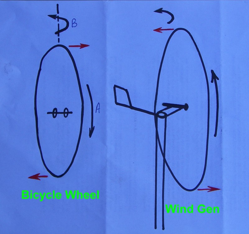
Take a bicycle wheel and spin it very fast say in direction 'A'.
Now rotate it about a vertical axis in direction 'B'.
RESULT:- Bottom will suck in, and Top will push out.
Recommendation:- Design your wind generators with a rotational direction that, with correct sided offset, causes the bottom to push out on entering furl. This could be a blade saver if you use close blade to mast spacing or flexible blades such as PVC.
Summary:
Clockwise rotating (looking from front) prop = left hand offset.
and conversely,
Anticlockwise rotating prop = right hand offset.
A good general rule to follow for all designs me-thinks.
Glenn, perhaps worth a line or two in the main site pages???
was working fine... til the smoke got out.
Cheers Gill _Cairns, FNQ
martinjsto Senior Member Joined: 09/10/2007 Location: AustraliaPosts: 149
Posted: 03:19am 09 Dec 2007
Copy link to clipboard
Print this post
very interesting gill i have tryed the bycical wheel and your right, so as speed increases the props will tend to tilt backwards and away from mast, this would also give the furling effect as well and would be governed by speed of rotation therefor windspeed, this should also be quite accurate furling at a fairly consistand point, you think that by pivoting the mill head verticaly might cause it to tip 90 degrees in strong wind? if so then the cable could becomes a problem?
martin
free power for all
McAlinden WA
GWatPE Senior Member Joined: 01/09/2006 Location: AustraliaPosts: 2127
Posted: 07:12am 09 Dec 2007
Copy link to clipboard
Print this post
Hi All,
I think this principle is used by the manufacturers who provide the tilt back furl mechanism. Soma, some AirX, Westwind have a model, and many others.
I have noticed that this mechanism does require a dampner and spring mechanism, and I have seen this fail, within 4 months at a good location for wind. The benefit of the tilt back design is the mill still continues to track the wind in furl.
I think that the side furl mechanism is more gentle on the mechanicals. The rotor blade has a much lower moment of inertia compared to a bicycle wheel, as most of the weight is in the alternator. I am sure a reader with a mathematical background could determine if the blade was a significant contributor to the mill total inertia.
I do agree that the PVC, or other more flexible blades can exhibit flutter etc in operation. I have seen fibreglass blades desintegrate. This could have been a result of the procession effect caused by the rotating disk being pivoted. The blades eventually hit the tower and failed. It was not determined what caused the failure, as not much was left to look at.
Strong blades seem to be the answer here.
Hey Martin, what cable would that be?
cheers, Gordon.
become more energy aware
Gill Senior Member Joined: 11/11/2006 Location: AustraliaPosts: 669
Posted: 10:51am 09 Dec 2007
Copy link to clipboard
Print this post
Sorry martin, you've missed the understanding of the process. Speed of rotation does not induce any forces that can be used for furling, quite the contrary, the faster the rotation the greater the gyroscopic resistance to furling.
What this little experiment shows is by it's gyroscopic resistance to yawing, perpendicular (pitching) forces are evident. These forces can be to our advantage or disadvantage depending on the rotational direction and yaw direction of the furl. We can use these forces at the time when most flex is on the blades due to high speed and furling.
There is no advantages for a pitching furl as the forces induce roll which has of no advantage for a lay back furl design.
Edited by Gill 2007-12-10was working fine... til the smoke got out.
Cheers Gill _Cairns, FNQ
GWatPE Senior Member Joined: 01/09/2006 Location: AustraliaPosts: 2127
Posted: 10:49pm 09 Dec 2007
Copy link to clipboard
Print this post
Hi Gill,
I have rigid carbon fibre blades on my mill, so I probably missed out on this sort of drama.
How much gyroscopic force is there on a mill rotor, considering most of the inertial mass is located towards the centre of the spinning disk? This is unlike a bicycle wheel, where nearly all the mass is located at the perimeter and contributes significantly to the gyroscopic effect.
cheers, Gordon.
become more energy aware
martinjsto Senior Member Joined: 09/10/2007 Location: AustraliaPosts: 149
Posted: 02:06am 10 Dec 2007
Copy link to clipboard
Print this post
ok gill i see the concept, clockwise direction lh offset tend to push blades in closer to pole, therefor posability of a strike. anticlockwise direction & rh offset should tend to push blades away.GWatPE statement is true, probably only advantageouse to those using pvc blades, mine i carved from lamminated beams so there very rigid.
i was thinking of the cable from the mill GWatPE, mine dosnt use sliprings so if as i originaly thought the mill tilted backwards from the g force the power cable might get tangled, thats not what happens,
the g forces produced by the rotation i thought i could use as a means of swithching between delta and star at a certain speed..
my idear was to use springs and weights along the lenght of the blades so when a certain speed is achieved the weights move out to contact the delta winding switch, as the mill slowed down the springs return weights to original position, whats your thoughts as a switching mill seems to be a easy way to increace efficiency?
free power for all
McAlinden WA
KiwiJohn Guru Joined: 01/12/2005 Location: New ZealandPosts: 691
Posted: 02:33am 10 Dec 2007
Copy link to clipboard
Print this post
This would be easy enough to make, maybe harder to make something durable. However I think the same thing could be done fairly easily in electronics and would not involve moving parts (apart from the relay armature of course).