Notice. New forum software under development. It's going to miss a few functions and look a bit ugly for a while, but I'm working on it full time now as the old forum was too unstable. Couple days, all good. If you notice any issues, please contact me.
KiwiJohn Guru Joined: 01/12/2005 Location: New ZealandPosts: 691
Posted: 06:41am 10 Dec 2007
Copy link to clipboard
Print this post
There have been a number of references to switching star to delta between high and low windmill RPM.
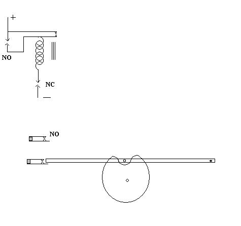
Probably the best way to do this would be with an electronic circuit monitoring the frequency of the alternator output but for those who would like a mechanical way of doing it I present this simple scheme:
There is a simple cam on the alternator shaft and bar, pivoted at the right hand end moves up and down as a pin follows the shape of the cam.
The moving end of the bar actuates two contacts, one normally open and one normally closed.
At low RPM the pin stays in contact with the cam and at the bottom of the stroke it touches and opens the normally closed contacts. At higher RPM the bar begins to 'float' and the pin loses contact with the cam and the bar no longer opens these contacts. At some point as the RPM increases the bar will float high enough to close the normally open contacts and when it does the relay will pull in and be latched by its own contacts.
The relay will stay closed until RPM drops and the bar again contacts and opens the normally closed contacts and so unlatches the relay.
Thats the general idea!
Tinker Guru Joined: 07/11/2007 Location: AustraliaPosts: 1904
Posted: 02:53pm 10 Dec 2007
Copy link to clipboard
Print this post
The mechanical side of my brain tells me that your system exhibits too much wear (on the contacts and bar/pin) to be long time reliable. I would sooner salvage the centrifugal switch out of a single phase induction motor and use that instead. It is, after all, designed to work for the expected life of the motor. And you could fiddle with the weights and/or springs to some extend to fine tune the switching point.
KlausKlaus
KiwiJohn Guru Joined: 01/12/2005 Location: New ZealandPosts: 691
Posted: 06:59pm 10 Dec 2007
Copy link to clipboard
Print this post
Ha ha, I knew there would be something wrong with it! Funny thing though the same principle seemed to work for about 100 years dinging the bell on the old cream seperator! The mechanical side of my brain tell me that if I wanted it to last forever I could put a small ball race on the pin!
The practical side of my brain tells me the switch from an induction motor does nothing except operate once at starting and would be rather difficult to incorporate.
brucedownunder2 Guru Joined: 14/09/2005 Location: AustraliaPosts: 1548
Posted: 08:16pm 10 Dec 2007
Copy link to clipboard
Print this post
Gee, I love that way you fellows are thinking, very interesting ideas lately on this forum ,keep it going .
I've the dual F&P up and configured into a 48v battery bank. My ABS plastic blades are around 11 feet and really start in a slight breeze. The voltage climbs very fast to ,say,50v and then starts charging at around 55 v's.. (battery is fairly low at present).
Hardly any noise,mainly because of the low operating rpm.
Ps.. fieldlines and this forum ,way back , had some discussion on the above idea's--but you'll have to do a search for those post's.
Great stuff
BruceBushboy
Tinker Guru Joined: 07/11/2007 Location: AustraliaPosts: 1904
Posted: 03:01pm 11 Dec 2007
Copy link to clipboard
Print this post
Cream separator, eh? Well, you got me there as I know nothing about these. But why on earth would you want a bell dinging on a separator escapes me, don't these things make enough of a racket on their own ?
Your practical brain side is spot on, the centrifugal switch operates (opens a contact) once a certain speed is reached and closes again if that speed reduces below that level. Is that not exactly what your speed sensitive star delta is supposed to do?
In operation, there is only the gentle wiping action of the contact arm on the circular actuator, very little wear there.
In contrast, a costantly bouncing switch arm *has* to be more wearisome and would, IMO, be as difficult to incorporate as my idea.
There, now we are even KlausKlaus
KiwiJohn Guru Joined: 01/12/2005 Location: New ZealandPosts: 691
Posted: 05:11pm 11 Dec 2007
Copy link to clipboard
Print this post
Cream seperator, you must be a young fellow from the city maybe? The handle on a cream sepearator must be turned at a minimum speed or else you get a big mess on the floor and to help you avoid this a bell 'dings' every revolution of the handle until you get it up to speed. The bell operates on the principle of a cam and floating lever.
The two contacts of my simple design operate at different speeds so that the cut in speed is lower than the cut out speed and of course these are adjustable by numerous means, moving the position of the contact assemblies, putting a weight on the arm, lengthening the arm, adding a spring.
Tinker Guru Joined: 07/11/2007 Location: AustraliaPosts: 1904
Posted: 02:33pm 12 Dec 2007
Copy link to clipboard
Print this post
Hi Kiwi John,
Old fart from the city more likely , thanks for the enlightening info on cream seperators. I vaguely recall seeing the process done once as a small boy where I grew up but they must have used different equipment as something like a bell dinging at every handle revolution surely would have stuck in my memory.
Interesting, the different activation speeds you mention but also getting too complicated.
Me now thinks a simple tacho chip (LM2917 I think?) would be easier to implement unless you have the resources of an instrument maker and your brother is a watchmaker Klaus
KiwiJohn Guru Joined: 01/12/2005 Location: New ZealandPosts: 691
Posted: 05:35pm 12 Dec 2007
Copy link to clipboard
Print this post
The cream seperator mechanism is very simple and is just a cam with a lever that strikes the bell, when the machine is up to speed the lever starts to float on the cam and stops making contact with the bell. So no bell per revolution except if you are turning too slow!
Haha, I can see me down in the shed one evening making one of these for demonstration purposes.
On a more serious note, I dont really see this as the ideal way to go, I only suggested it for those who may be just a little hesitant to try soldering ICs using the plumbers soldering bolt that great granddad left on the farm.
Gill Senior Member Joined: 11/11/2006 Location: AustraliaPosts: 669
Posted: 02:19am 15 Dec 2007
Copy link to clipboard
Print this post
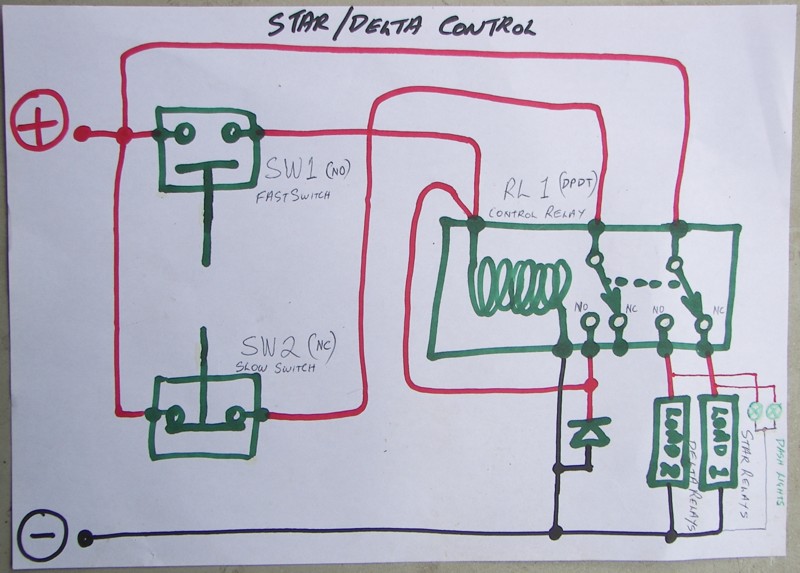
A workable mechanical approach to Star/Delta switching there John.
Your circuit is a bit vague though, so here's my vague circuit too.
Am considering whether to retro fit one of these to GillMill_1 ........ But So Many Projects on the GO!!!???
was working fine... til the smoke got out.
Cheers Gill _Cairns, FNQ
KiwiJohn Guru Joined: 01/12/2005 Location: New ZealandPosts: 691
Posted: 05:25am 15 Dec 2007
Copy link to clipboard
Print this post
You schematic is so much nicer than mine Gill, did you draw and scan that?
I have been thinking about this mecahism and I think the shape of the cam I showed is way more than is necessary, in fact I suspect just a circular cam with an off centre axis would be sufficient and the switches could be micro switches mounted on a backing plate.Edited by KiwiJohn 2007-12-16
Gill Senior Member Joined: 11/11/2006 Location: AustraliaPosts: 669
Posted: 08:15am 15 Dec 2007
Copy link to clipboard
Print this post
Yes John, my thoughts were to use micro switches too.
Many versions of cam idea, in fact, need not be a cam but a grooved track would work as well with the lever pivoting forward and back instead of up and down.
So long as there is still the motorbike jump effect off the cam ramp at higher speeds.
Scanner is dead like the printer so sketch and photograph page is the work-around. So much faster than graphics programmes to get a simple ideas across. was working fine... til the smoke got out.
Cheers Gill _Cairns, FNQ


 The mechanical side of my brain tell me that if I wanted it to last forever I could put a small ball race on the pin!
 ?
?

 , thanks for the enlightening info on cream seperators. I vaguely recall seeing the process done once as a small boy where I grew up but they must have used different equipment as something like a bell dinging at every handle revolution surely would have stuck in my memory.

 did you draw and scan that?