Notice. New forum software under development. It's going to miss a few functions and look a bit ugly for a while, but I'm working on it full time now as the old forum was too unstable. Couple days, all good. If you notice any issues, please contact me.
Tinker Guru Joined: 07/11/2007 Location: AustraliaPosts: 1904
Posted: 03:08pm 19 Dec 2007
Copy link to clipboard
Print this post
First of all let me say that Gizmo's detailed instructions are excellent and with these my 7ph rewiring worked first time.
But the method shown is best suited for a permanent connection, if one wanted to experiment with independant, star or delta connections it can quickly get a bit messy and very confusing.
Below are some photos of how I overcame that.
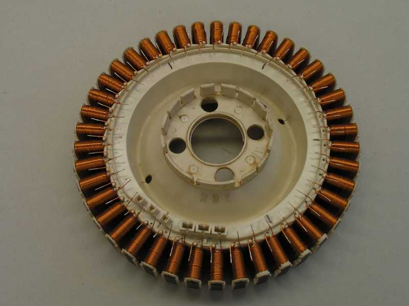
You may have seen a pic of mt F&P stator in another message here, I have now removed all the starpoints that were shown there.
But lets start from the beginning here, for those who are just starting out.
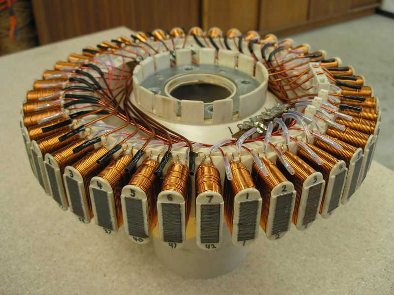
After all the original factory wire links were cut I wound all the coil finishes (the wire that finishes on the top layer) a half turn around the little plastic post so that its end faces OUTWARD in between the coils. This end was fixed to the post with a drop of epoxy glue (Araldite).
All the coil starts were carefully bent so the faced inwards, towards the centre of the rotor.
Doing it that way I think 50% of the confusion of the 84 wire ends was sorted .
Next the enamel was carefully stripped off the wire ends and they were tinned. Do place something like a cardboard strip under the outward facing wires when stripping and tinning, it is very difficult to remove solder blobs that may drop down the coil sides.
Next came the marking of the coils, there are two places on the pole face of the coil former where one can write with texture pen. I numbered the coils from 1 to 42 on the lower side and in repeated sequences of 1 to 7 on the upper. This helped a lot when connecting the wire links.
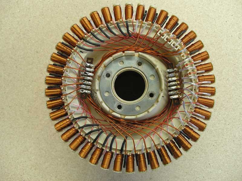
To connect the coils together I used short pieces of enameled wire. Yes, its more bothersome to strip and tin the ends of these but the wire has a small diameter and makes for a tidy wiring job. There were 21 links to connect the coils in series, I made them all the same length so they can be done in a batch.
For the paralleling of the coils I used thicker enameled wire, there were 28 longer links, also done in a batch, all the same length. Just be careful to work out the length of the first one before you cut the lot too short or too long.
The parallel connections were terminated on a 7 lug tag strip.
The old star connection I mentioned above was connected exactly as the paralleled ends described above and also terminasted on a 7 way tag strip.
So I ended up with symmetrical wiring at each end of the coils, giving me 14 tag strip terminations.
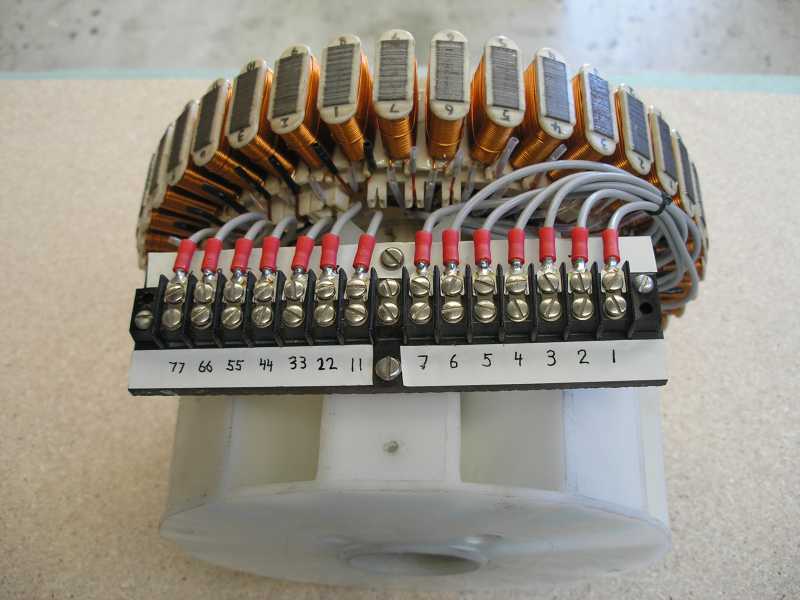
This looks a bit complicated but it really is not, quite logical once started. From the tag strips 14 short flexible wires led to a screw terminal strip that can be conveniently accessed while the generator is tested.
I used a different convention to name the terminations, letters seemed too confusing. So I numbered one tagstrip (all the start ends of the coils) from 1 to 7 and had corresponding double digits (11, 22,33...) at the other strip where all the coil finish ends were terminated.
To test, see if there was a connection between 1 and 11, between 2 and 22 and so on.
The advantage of this setup is that one can either use the coils independantly by connecting a pair of diodes at each screw terminal (28 total), or in star by linking all 7 of either the single digit or the double digit terminals.
Of course, connecting it up in delta is also a breeze, one just needs to insert seven links at the terminal strip.
How this is done and circuits of the above will appear in another message. I need to do some more testing first to see if my delta connections are correct - the star arrangement works just fine.
KlausKlaus
Gill Senior Member Joined: 11/11/2006 Location: AustraliaPosts: 669
Posted: 02:21am 20 Dec 2007
Copy link to clipboard
Print this post
Nice neat job there Tinker. Four stars from me
I'd be a little concerned the enamel would rub through in places with vibration over time, but I see no reason that insulated wire would not work as well to pacify those with that worry.
Another suggestion, I use a hot glue to brace connections and runs of wire such as yours. Not so impressive to look at then, but more secure.
I like the idea of twisting the wire back around the post. Gives excellent separation for connections.
Good idea. Well Done. was working fine... til the smoke got out.
Cheers Gill _Cairns, FNQ
Tinker Guru Joined: 07/11/2007 Location: AustraliaPosts: 1904
Posted: 12:42pm 20 Dec 2007
Copy link to clipboard
Print this post
Thanks Gill, four stars eh? Good idea about the wire bracing. at the moment they are coated with insulating varnish (invisible to you ) and it seems to bind them well enough. But I will add further bracing once I'm finished testing and happy with the configuration.
KlausKlaus


 .
.