
|
|
Forum Index : Windmills : 12v rewire v’s 48v rewire for charging
| Page 1 of 2 |
|||||
| Author | Message | ||||
martinjsto Senior Member Joined: 09/10/2007 Location: AustraliaPosts: 149 |
hi all, i recently put up my new 7 phase wind generator made as reccomended for the 12v or 24v systems a 7p2p = 3 groups of 2 poles with the new rotor. i have found that i only seem to charge my 24v bank of batteries for a few secconds during windy days. the mill spins realy easy in the lightesr of breeze but the voltage at the batteries only increases for a few secconds at max rpm. i dont have any way of measuring the rmp in situ, but it realy spins fast to the point of not being able to see the individual blades. open voltage peaks at about 42vdc so far as i have seen but i have also seen my mill run much faster in realy blowing conditions. my thoughts was to rewire to the 48v system ie the 7p6p = 6 poles wired in series. Max volts, good for slow running windmill. 48v systems. is this suitable for a 24v system? this should give me better charge through lower wind speeds, am i correct?. will the higher voltage be damaging to my batteries, i have a dump charge controler system that regulates the charge between 24 vdc to 30vdc the charge controler workes perfectly on the test bench. whats your thoughts, if this works well why make a lower voltage units, or will i sacrifice amps for voltage. i was thinking that it is better to get lower amps all day charging than a high amp for only a few minnuts a day. \ martin free power for all McAlinden WA |
||||
| brucedownunder2 Guru Joined: 14/09/2005 Location: AustraliaPosts: 1548 |
Hello Martin,, I had this same problem for many months and with different blades. I tried 12 v ; then 24v . Like you ,the mill would only punch out power for very short durations. I finally was persuaded to switch to 48v .Built a new battery bank and got hold of a 48v inverter. Built a big set of abs plastic blades ,,3 mtr's dia or a bit more. Reconfigured the F&P stators into 7/2 and built a dual set-up. put the diode bank up at the platform and run 48v dc down to the battery bank..Series the 2 stators after the diodes. Well,,, in the slighest of breeze this thing get a go on and climbs to 60 v's real fast, giving out around 50-300 watts. Not a lot ,but ,at least it's maybe better than sitting there motionless for days on end. Also ,,very important,,it's almost silent ,,just the slighest noise when furling. (this has more work to be done).. I feel there's more power available ,,but that needs working on also--maybe different windings,Etc. PhilM has a similar set-up ,he has pictures ,search on this site for them. Well,there you go , good luck Bruce Bushboy |
||||
Gill Senior Member Joined: 11/11/2006 Location: AustraliaPosts: 669 |
G'day Martin, You indicate an open circuit voltage of up to 42 volts, so you must have a fair current passing through the battery. At no time do you quote an amperage, implying a rise in battery voltage as your method of assessing generator output? Sorry, this is inadequate for assessing performance of a generator and making reccomendations. was working fine... til the smoke got out. Cheers Gill _Cairns, FNQ |
||||
| martinjsto Senior Member Joined: 09/10/2007 Location: AustraliaPosts: 149 |
thanks for the reply guys, sounds like a good setup bruce, if i did the same, couldnt i keep the 24v batterys and get a better charge out of the 48v unit?. my blades are about 2.5m diameter but seem to work well on 12v. sorry gill maby i can clarify a bit, i figured that if the mill has open voltage of 24vdc and i connect to batteries i should be charging the batteries (2 banks of 12, 2v * 380amphr x telecom) @ 1 amp; 48vdc at 2 amps, etc so i should be getting aprox 1.75amps at 42v. i maby be wrong about the amp/volt relationship does it depend on the state of charge?. i have connected an amp meter to see the amperage but rarely get a reading as the voltage only peaks for a few secconds. i have tested this unit on a lathe b4 assembling and again b4 lifting into position both times the output of the mill is in excess of 100vdc at 480 rpm open voltage, 24vdc is shown on the multimeter when I connect to 24 v bank of batteris, the amps are about 3.5 when connected (loaded)on test bench at that rpm. i have 3 blades on the mill i hand carved following the instructions on this site and have worked realy well whilst they were on 12v system maintaining a great charge for my 12v lighting system, i recently upgraded to 24v and run a 24v 4000w inverter and consequently upgraded the mill to 24v also. thats when i noticed the lack of charge, i disconnected the batteries from my solar grid to only the mill, the mill ran all day in good wind but the voltage didnt move. the same battery bank is connected to a 320w solar grid and will charge no problems when set to solar. im just not sure of the best combination and weather the 48v will charge the 24v batteries better. martin free power for all McAlinden WA |
||||
| matt down south Regular Member Joined: 20/10/2007 Location: AustraliaPosts: 50 |
hi Martin try 7p3p=2 groups of 3 poles for the extra volts down in the rpm range with a 80 series stator,it should start charging in the low 100 plus revs but runs out of puff above 500 rpm,for a high speed mill try a 100 series stator wired the same 7p3p.With the 80 series 7p2p i rewired and run on my stationary motor powered test bench it didnt get to 24v but when the batts were in 12v mode it charged the batts quiet nicely with a low rpm cutin 100 plus rpm,give it a go and get back to us on how it went! Pt wakefield Matt matt |
||||
| martinjsto Senior Member Joined: 09/10/2007 Location: AustraliaPosts: 149 |
thanks mat, i am using a 7p2p at the moment and also have a 100 series yet to wire, i will try wiring it as a 7p3p as you sugested, and will get back to you thanks again i have uploaded some vid on you tube if anyone care too see. sory for the quality see http://au.youtube.com/profile?user=martinjsto martin free power for all McAlinden WA |
||||
Highlander Senior Member Joined: 03/10/2006 Location: AustraliaPosts: 266 |
G'day Martin, you must have a wiring problem, if your spinning it on a lathe at 480rpm and your getting 3.5 amps, that's only 84 watts @24v. You should get around 200 watts with a ceramic magnet rotor. Check each phase and see if they are even. I'de stay with the 80 series, thay produce higher volts for the same rpm. Central Victorian highlands |
||||
| davef Guru Joined: 14/05/2006 Location: New ZealandPosts: 499 |
Open circuit (o/c) voltage tells you nothing about the power you can get from the system. For example, 10 * 1.5V AAA cells deliver about 15V o/c. 6 * 2.2 550Amp/hour lead-acid cells also deliver 15V o/c. Which one can deliver more power? To determine the maximum power you can get from a given generator (or source), load the unit down until the o/c voltage drops to 1/2. The value of load resistance will equal the source resistance of the generator. From this you can work out the current the generator could supply to various loads, ie your 15V battery. What is the battery's internal resistance? Probably much lower than your generator source resistance, so you have to limit the current into the battery in order that the generator's loaded voltage doesn't drop below 1/2 or you won't be getting maximum power into your battery. N.B. a 20V o/c generator MAY deliver more power to a 15V battery than a 40V o/c unit. And vice versa. You gotta' know the source resistance. State of charge will have a minor effect. Keywords: Ohms Law and Maximum Power Transfer Theorem |
||||
| martinjsto Senior Member Joined: 09/10/2007 Location: AustraliaPosts: 149 |
thanks dave i will test unit in lathe using the method you outlined. thanks highlander, i have checked motor for wiring faults but all seems good, i think that the problem is that i was just checking the amps going into batteries. you see i had the gen in a lathe doing 480 rpm and the rectified output linked directly to the batteries that were already 95% charged, i then just put in line the amp meter to read 3.5 amps, but as dave mentioned the gen wasnot loaded down to 50% of output voltage. i will do further testing and report back martin free power for all McAlinden WA |
||||
| matt down south Regular Member Joined: 20/10/2007 Location: AustraliaPosts: 50 |
hi Martin you never ever tell us the volts as well as amps so we could calulate watts [volts times amps = watts]you need 2 m/meters for this. your 80 series stator at 480 revs would be running out of puff,did you do the 7p3p rewire as disgust before or are you still testing the 7p2p setup? build your self a stationary motor powered test bench and youll be able to vary the revs to plot the cutin revs to max output to the point it where it goes off song.id share the findings with the group but cant get done to my farm where i left the book its in.you will need another meter with frequency on it and ask Gill for the calulation to revs. Pt wakefeild Matt matt |
||||
| martinjsto Senior Member Joined: 09/10/2007 Location: AustraliaPosts: 149 |
Hi all, reading the problems and discussions you guys tackle makes me realise how little i know, sory for the lack of info i will try to provide better test results. well I have been testing my units in the lathe as discussed, I am testing the 7p2p and 7p3p 7 phase with new rotor. firstly I found that I had a great deal of belt slippage on lathe when generator was loaded, I put on a new drive belt for the lathe and started testing. First test is the 7p2p. The o/c is 54 to 55 vdc. I then loaded with 4off, 12v*50w spotlights wireing 2 together in series for 24v at 50w, then both sets wired together in parallel, should be a load of 24v at 100watts i believe and reduce o/c to about half. I got 8.41 amps and 27.3 volts on multimeters. Lathe is set at 480rpm but slows down to about half that when loaded. Both generators im testing are 80 series 7 phase using new rotor. gill could you please suply me with the calculations for correct rpm. and how do i test for frequency? hope this is better info. 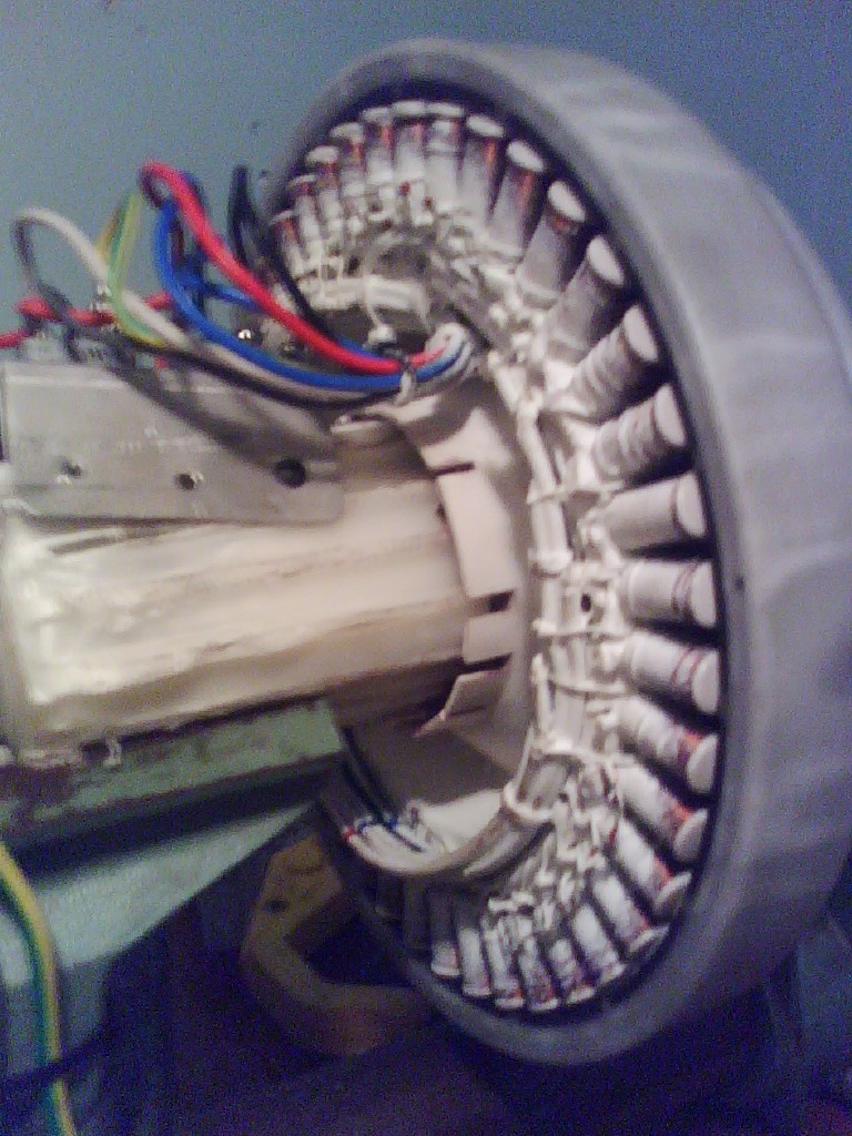
the test unit a 7p2p on lathe 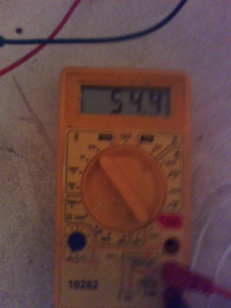
o/c at 54.3v 
volts 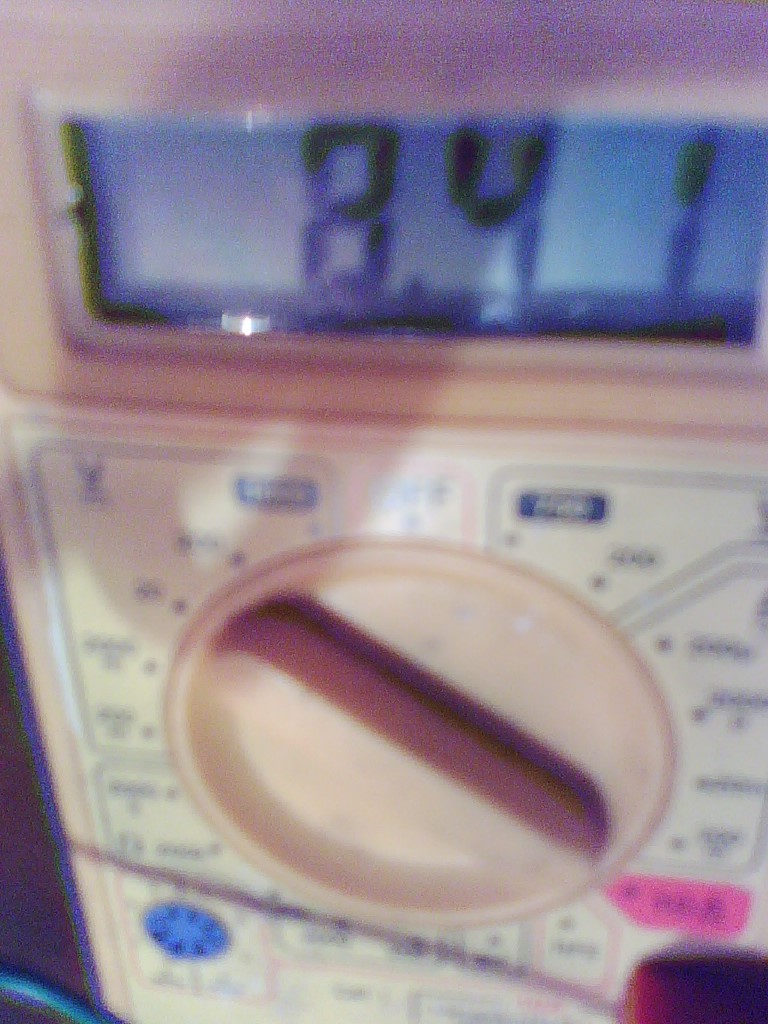
amps 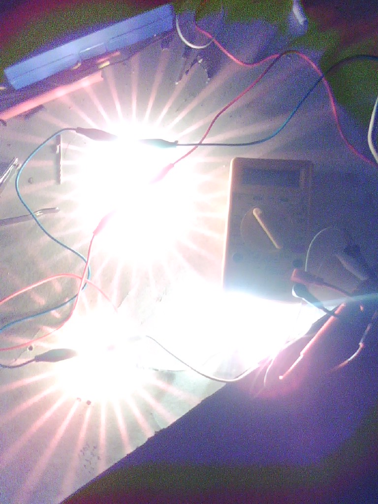
seems lots of power 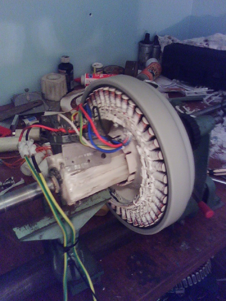
slowed down to about half speed 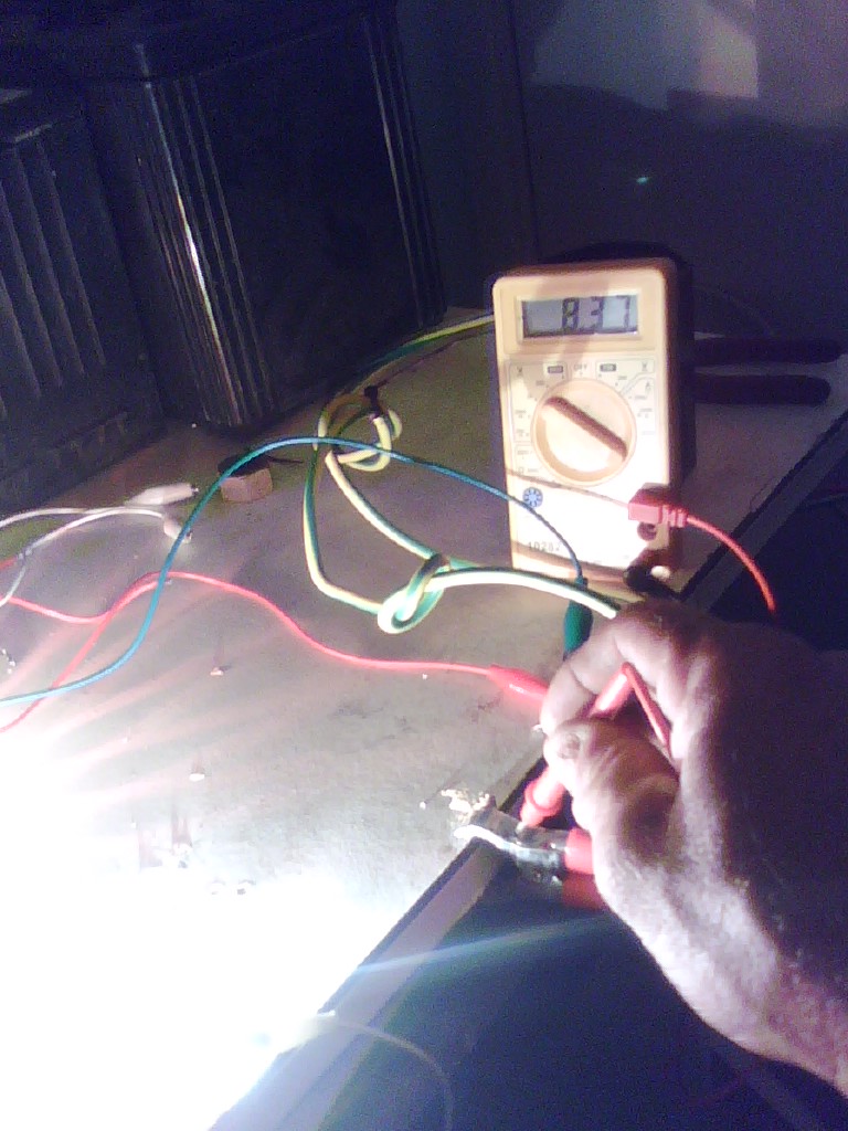
8.37 amps the 7p2p i am testing seems to charge mt 24v batteries quite well in this enviroment, i will hook up the 7p3p tomorro and report back my findings thanks heaps martin free power for all McAlinden WA |
||||
| martinjsto Senior Member Joined: 09/10/2007 Location: AustraliaPosts: 149 |
sory for the pic size, i will shrink them next time free power for all McAlinden WA |
||||
| Gill Senior Member Joined: 11/11/2006 Location: AustraliaPosts: 669 |
Martin, For RPM reading calculated from the Hz reading of your Multi Meter, download http://www.supernerd.com.au/~giladams/RPM using DMM.doc Sorry the post a hyperlink button won't work. When using delta, a problem can arise and that is the Hz reading is way higher than expected. It can be a fluctuating reading, but often a multiple of the expected Fq. I have found reducing the phase voltage being metered reduces the circulating harmonics as well to a level that no longer exceeds the threshold. To do this add a 100k resistor to each meter probe. The multimeter in your pics will not read Hz. Cheap ones that do are about $30 was working fine... til the smoke got out. Cheers Gill _Cairns, FNQ |
||||
| Highlander Senior Member Joined: 03/10/2006 Location: AustraliaPosts: 266 |
That's better, 27v times 8.37A =225 watts Now you need to find to revs of where it starts to charge your batteries. Can you post a pic of your blades? Central Victorian highlands |
||||
| martinjsto Senior Member Joined: 09/10/2007 Location: AustraliaPosts: 149 |
thanks gill, highlander i will pick up a multimeter that has hz and do the tests, it would be good to know the exact rpm i am getting these results on. the doc is great thanks gill. i going to mod my lathe to reduce the spindle speed, just need to get a different pully combination then i can find the start of charging rpm. i dont have any good pics of my blades, i will get some next time im at my block and post, i have to drop the mill anyway to swap over the generator to this one im testing. i did the calculations for maximum power using the results above for the 7p2p. i first calculated source resistance using davef statement: load the unit down until the o/c voltage drops to 1/2. The value of load resistance will equal the source resistance of the generator. load resistance equates to 2.89ohms. i used the formular for pmax found here http://www.tina.com/course/11maxim/maxim.htm pmax=o/c voltage squared divided by 4 then multiplied by source resistance Pmax = 54.4*54.4 = 2959.36/4 = 739.84 * 2.89 = 2138.13 is that watts? i have started to test the 7p3p today and got some interesting results. 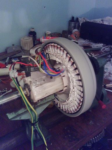
lathe setup 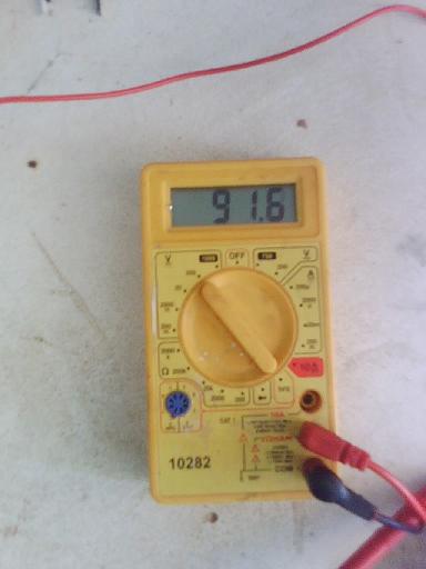
7p3p oc volts 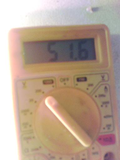
7p3p loaded volts 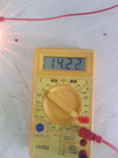
7p3p loaded amps 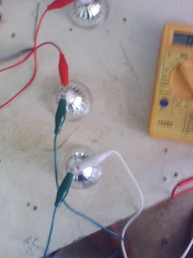
7p3p load setup the o/c is 91.6v on a load of 3*12v 50w downlights wired in series amps on multimeter was 14.22 amps volts on multimeter whilst loaded is 51.6 this gives a source resistance of 3.63ohms form there the power max should be 2236.55 am i correct with my calculations, if this is watts then theoretically these can produce 2kw? martin free power for all McAlinden WA |
||||
| KiwiJohn Guru Joined: 01/12/2005 Location: New ZealandPosts: 691 |
Ummm, I think something is wrong (or maybe I dont understand) 14.2 amps through the lamps in series is surely not right? With lamps in series the current they could handle would be the same as a single lamp, i.e. about 4.2 amps. |
||||
| GWatPE Senior Member Joined: 01/09/2006 Location: AustraliaPosts: 2127 |
Hi Martin, The 12V bulbs give 50W consumption when connected to a DC supply of 12V. You are not supplying a pure DC supply as indicated by the 3 bulbs in series across an indicated 51.6V. Your multimeters are not able to show the RMS volts or amps. If the readings were true then one of the light bulbs would fail. A good indication of your meter reading incorrectly are the clip leads. The ones you are using are rated for about 4A. Ohms law, V = I x R I = V / R and Power = V x I = I x I x R = V x V / R The link http://www.tina.com/course/11maxim/maxim.htm is not clear in the formula with placement of operators. You will probably find like others that at the RPM you are testing that you will be producing 150-200W as indicated by the light bulbs. Don't despair too much by the readings indicated by your meters. The meters are OK for pure DC or pure sinewave AC. A rectified generator output is neither. Good luck with future testing. Gordon. become more energy aware |
||||
| martinjsto Senior Member Joined: 09/10/2007 Location: AustraliaPosts: 149 |
hmm ok I will definatly need a new multimeter. in the meantime, i thought i will just keep loading the generator up and physicaly see what load it will suply. so far i have run 2*24v 100 watt spotlights in parrallel so must be getting 24v at 2* 4.16amps = 8.32amps therefor 24*8.32= 199watts if i can get 5 to 8 amps into my batteries i will be very happy. obviosly this is static testing in lathe not on windmill so rpm will fluctuate on mill. my next test will be with new multimeter, when i can afford one. thanks all for your assistance. martin free power for all McAlinden WA |
||||
| davef Guru Joined: 14/05/2006 Location: New ZealandPosts: 499 |
[Quote]A good indication of your meter reading incorrectly are the clip leads. The ones you are using are rated for about 4A.I think it is a "long stretch" to judge meter accuracy on the rating of the clip leads! Either you have to do some proper AC measurements or rectify to DC and put a BIG electro on the output to reduce any ripple voltage to a low enough level and then do the measurements at DC. Rectifier losses would need to be taken into account. Proper AC measurements . . . would require you knowing the waveform, ie harmonic levels present in the 3 phase output. I'd try a digital oscilloscope, like the Tektronics TDS series and look into it's math functions to see if it could do calculations on the waveform to work out average or RMS voltage. Then make a current sense resistor or shunt up so you could measure current, using differential inputs on said 'scope. Think I'd be doing DC measurements, then you could use your current multimeter. You probably have diodes around. The filter capacitor required, if you trying to suck 200 Watts out of the generator will probably be quite big, i.e. 10,000uF rated at, say 25% higher then the highest DC voltage you expect. A bit of ripple, say less than 0.5 to 1.0Volts (there's that 'scope again), should not influence your D.C. readings much. Happy experimenting! |
||||
| Gizmo Admin Group Joined: 05/06/2004 Location: AustraliaPosts: 5182 |
This is a good thread, good to see the experimenting going on there Martin. It looks like you converion is working fine. I've had over 340 watts from a 7 phase into 12 volts, but I think it could do a lot better into 24 volts, not bad for ceramic magnets. Comming to grips with current, voltage and AC readings compared to DC readings can seam a little confusing at first, but it will all make sense one day. The guys are right, measuring the AC directly can give miss leading readings, its better if you can connect the 7 wires into a 7 phase bridge, then connect the DC output across a capacitor or battery. Then your readings will make more sense. Also watch out for any bare connectors, that 7 phase alternator will give you a very nasty shock if your not watching what your doing. Glenn The best time to plant a tree was twenty years ago, the second best time is right now. JAQ |
||||
| Page 1 of 2 |
|||||
| The Back Shed's forum code is written, and hosted, in Australia. | © JAQ Software 2026 |
