
|
|
Forum Index : Windmills : Homemade Stator/Rotor for Savonius
| Page 1 of 2 |
|||||
| Author | Message | ||||
Tinbender Newbie Joined: 03/02/2008 Location: United StatesPosts: 14 |
I am kicking around an idea to build a homemade Stator/Rotor for a Savonius. The Stator/Rotor's diameter can be as large as required to be able to use whatever number of coils and/or magnets required to cut-in at various rpms as the wind speed increases. Stretch out a 36 pole, 10 inch diameter F&P stator, over a 3 foot diameter area, then make a Rotor to match that diameter. That rotor could hold 3 times as many neo magnets than a converted F&P Rotor. Without increasing the number of Coils we have increased the number Magnet Passes Per Coil Per Revolution(MPPCPR) by 3 times. This alone, if the coils were wired to utilize this increase in passes without stalling the Turbine, would solve the problem of a low RPM Savonius. Extra Coils could also be added to the Stator and various Coil group configurations could be wired to various cut-in RPMs throughout the range of wind speeds available. The highest speed cut-ins could be wired to extract maximum power with little worry of stalling. A mix of Iron-Core and Air-Core Coils might have to be utilized to overcome a cogging problem, although there may be a Iron-Core Coil to Magnet ratio that would overcome cogging. Would need some tinkering. Probably has already been done.. I'll have to search the web. VAWTs Up Doc? VAWTs Happening? Is that VAWT you vant? VAWT vere you thinking? |
||||
azland00123 Newbie Joined: 24/02/2008 Location: United StatesPosts: 23 |
I don't under stand what "cut in" means. Is it the point where the unit begins to generate power? I assume from the other threads that at that point the load on the f & p can become to great and over come the force the blades are exerting causing them to stall out? Bob |
||||
wind-pirate Senior Member Joined: 01/02/2007 Location: CanadaPosts: 101 |
Kind of close Bob. When the voltage of the generator reaches that of the battery bank to start the charging process. Ron THE Pirate. stealing wind & solar energy is fun |
||||
| wind-pirate Senior Member Joined: 01/02/2007 Location: CanadaPosts: 101 |
Hi Brian The more mags and coils the more drag. The bigger the vawt needs to be. What we need to do is find a way to increase the speed of the vawt. Ron THE Pirate. stealing wind & solar energy is fun |
||||
Gill Senior Member Joined: 11/11/2006 Location: AustraliaPosts: 669 |
I tend to agree with the concept tinman is proposing. I have put the same idea forward previously. It is not so much the vawt that needs to spin faster but the generator. The use of step-up transmissions achieves this but at the cost of added load not present in direct drive methods. Counter rotating turbines is a method of doubling generator speed for a given vawt swept area by a direct drive method. Another is to increase generator diameter. It is after all the large diameter of the F&P motor that helps makes it so suitable for wind power generation. Let us not assume that an increase in diameter with it's increase in number of coils and magnets means the same magnets and the same coils, else we will have the situation wind-pirate warns us of above and as tinman says, it will stall. Also the assumption that tripling the circumference will triple the wire and magnet costs is also false. With so many more coils the amps each will carry is less so the wire gauge will be reduced. As a ball park figure I estimate the kg of copper to be the same as say a geared generator fitted to the same turbine. It can after all only convert the same kw of wind power available into kw of electrical power. (OK, so just a little more as no transmission losses but not x 3). Perhaps magnet strength can also be reduced to 1/3 for the same reason. Handy for $ as you'll need x 3 as many. One issue of concern to me with this idea is maintaining a consistent rotor/stator gap over a large diameter. In using a large dia generator on a water wheel I suggested to have a floating stator that rode like a tethered train on a rotating track and magnet rotor. However I think this idea does not suit the higher speeds and smaller diameters of a vawt, but it is one example of maintaining a stator/rotor spacing in a large diameter environment prone to warpage error. EDIT added comment: On rereading tinmans post I now see he was proposing to expand the basic F&P structure to a larger diameter. I guess this will produce a higher voltage peak and then a pause in the cycle. I'm likening it to PWM but in altered sine wave instead of square wave. volt peaks will increase but amps will drop relative to a standard sized F&P at the same rpm. And that's what's needed for battery charging at the slower vawt rpm's. Will have give this idea some more consideration as not 100% sure of it yet. As wind pirate says cogging will be more of an issue with this one. was working fine... til the smoke got out. Cheers Gill _Cairns, FNQ |
||||
| Tinbender Newbie Joined: 03/02/2008 Location: United StatesPosts: 14 |
If we expand the exact F&P structure to a larger diameter, the main difference would be that there would be a greater space from coil to coil and from magnet to magnet but the drag would be about the same. There may be less crossover magnetic field between the mags and coils but lets not focus on this for now. The main objective would be to increase the number of coils and/or magnets in this added space. Just adding magnets alone would cause more drag because of the greater load that would be producing more electricity. The added iron-core coils and/or magnets would most likly cause the turbine to not move at all. To remedy this we would have to use the maximum amount of iron-core coils(ICC) as would allow the turbine to turn in low winds and from there add air-core coils (ACC). ACC coils don't cause cogging or drag until a load is applied. An unlimited number of ACCs could be used and not affect drag or cogging and could be wired to cut-in at various turbine speeds. My question would be whether a set of ACCs putting out voltage, but not enough voltage to start charging(not reaching cut-in yet), would be causing drag? If not, then the additional ACCs could be grouped and wired to cut-in at incremental speeds, up to the survival speed of the turbine. The group of coils targeting the survival speed could be designed to cause maximum power output, with no concern for stalling or drag, and apply maximum braking force for survival of the turbine. Usually an alternator will produce power pretty well at a given RPM and after a certain speed increase it will not produce additional power as one would expect with the increase of RPM. That is because it is designed to perform at a given range of RPMs. With extended sets of coils we could target more than just one given range of RPM, and target higher than average to extreme RPMs when the stronger winds pick up. It's a shame to let all those strong winds pass us by with out capturing that power. VAWTs Up Doc? VAWTs Happening? Is that VAWT you vant? VAWT vere you thinking? |
||||
| azland00123 Newbie Joined: 24/02/2008 Location: United StatesPosts: 23 |
Ron does not call it "capturing" He call it "stealing"! I like the idea of stepping up the speed slowly and then pushing the limit to extreme. Its an interesting way of trying to achieve it. why not use all air core coils? Bob |
||||
oztules Guru Joined: 26/07/2007 Location: AustraliaPosts: 1686 |
Tinbender, I think once you start to build a new aternator from scratch (which is really what you are doing), you would be best to avoid anything to do with the F&P design. Apart from it's inexpensive procurement angle, and cute and compact size, it has not much going for it as compared to neo/aircoil machines. It has reluctance, hysterisis, iron drag, eddy currents, cogging and poorish magnets and lossy wiring.... but it is a cheap start point. and that papers over some of it's shortcomings. If you wish to design for a large alt. radius machine, with no iron loss, no iron drag, no eddy current loss and no cogging, a simple large diam axial flux will give the best results for a given input... and there is only bearing drag before cutin speed. (If you use very thick wire >2mm or ribbon wire, you may find some eddy drag at high rpm (with a VAWT???).. that sort of thing, but that scenario is most unlikely here) A vawt is up against it for output from before you start to build it..... low rpm and poor conversion of wind to mechanical energy and most importantly, most people seem to think it can generate significant amounts of power on the ground.. and nothing is able to.. compared to the same thing up high. ie it is a poor performer compared to the HAWTs before it starts life. It needs every advantage it can get, and the first things to get rid of are all the negative things which are inherent to iron construction gennies, of which the F&P is one example. I know they are held dearly here, but so are internal combustion engines. At least with wind gennies there is a better alternative, so far for internal combustion engines we have yet to see. So a simple dual axial or even single plate axial will (roughly half the output) allow the VAWT at least a chance of developing the best it can, with the least losses, and most scope for modification..... easy stator rebuilds, airgap adjustment etc. I like the idea of large radius alternators, but it is in your interests to keep the iron well out of the picture for both mechanical (cog vibration), efficiency, and ease of redesign and sloppy tolerances. .........oztules Village idiot...or... just another hack out of his depth |
||||
| Tinker Guru Joined: 07/11/2007 Location: AustraliaPosts: 1904 |
Oztules, to generate any electricity with rotating machinery you need a coil passing (cutting) through a magnetic field. Now, I seem to recall that magnetic flux passes through iron about 10,000 times easier than it passes through air. So, your neo/aircoil alternator has a very big hurdle to jump over right at the start, it requires VERY powerful magnets and rather thin coils. The magnets are available but one wastes a lot of their potential with any excessive air gap. Thin coils are not very efficient and hard to design so that all the available magnetic flux passes through the coil centre. I have built two smaller axial flux air coil alternators, a twin rotor and a triple rotor design and both were rather poor performers. Tinker Klaus |
||||
| Tinbender Newbie Joined: 03/02/2008 Location: United StatesPosts: 14 |
I like the Idea of the Dual-Rotor Axial Flux Alternator(DRAFA). I believe that is what I'm after. Some folks have had good results with it. These folks here made a DRAFA for their steam engine, which they say was almost exactly the same as the one they build for their Windmill, except for the way the coils were wound.Duel-Rotor Axial Flux Alternator otherpower.com group Something they said got me thinking about something. "The stator is identical to those we build for larger 17' diameter wind turbines with the exception...and wound the coils a bit differently. These coils are wound with 4 strands of #15 gauge wire (equivalent to 9 gauge wire) and there are 40 turns per coil." What came to mind was when a coil is wound with smaller gage wire, it produces more power but there is more resistance and heat losses and a limit to the amps a given coil can carry without fusing. So.. My question is... if a coil was wound with small gage wire with many turns, then cut through all the wires at one end where the magnet's flux doesn't pass, and connect all the ends together, would this solve the problem of resistance and let a higher amperage to be carried over many parallel single loop coils? Here's a pic.. 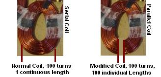
Using the coil on the left for example is a normal coil, but it is really just many single windings all hooked in series, so I will refer to it as a serial coil. The one on the right has been cut at one end and as in the picture has had the ends wired together so that all the single loops are wired in parallel. So what I am thinking is that the coils in a stator can be wound with many turns of fine wire without worry of amps burning out the wire because there is very little resistance in a 1 loop wire. what, maybe a 5 inch loop? Now that I fried my brains thinking this up, tell me what you think. Brian VAWTs Up Doc? VAWTs Happening? Is that VAWT you vant? VAWT vere you thinking? |
||||
| GWatPE Senior Member Joined: 01/09/2006 Location: AustraliaPosts: 2127 |
Hi Tinbender, The coil you describe will produce a higher voltage. The power is related to the load applied to the coil. The coil structure you have proposed with your photo will perform very badly. The individual strands of the parallelled wire will not be in the same magnetic field strength. This is basically why the original 100 seriesed turns produce a sine wave voltage output. What you have proposed will be effectively shorted turns. A single turn will also only provide one hundredth of the voltage with 100 times the current. The Flux design from otherpower produces a sinisoidal voltage output also. I spent the better part of 1994 designing and prototype testing coils and magnets before I settled on my 4 phase ironless axial flux design. I have previously described many of the aspects. Wire cross section becomes an increasing problem as magnetic field strength and flux alternating frequency increases. The final product is a usually a compromise with an air cored design. I found that the increase in magnetic field strength as the air gap decreased was offset by the reduced mechanical strength and number of turns in the copper coils for a designed operating voltage. I settled on a 3mm airgap with a total of 187 turns per phase giving a loaded output of 30V @ 4A at 500RPM per phase. I did find that overlapping coils provided a higher mechanical strength and so a thinner airgap could be used, with the advantage of less coils and a higher volts per turn. I also found that the geometry was especially critical if any coils were parallelled. I settled on a series arrangement of coils, due to the difficulty of making a coil/stator that had no rigid former. If I was to look at alternator design for a VAWT I would consider a radial design with magnets on the outside of a central rotor with coils arranged around the outside, with iron cores. It is easier to align from a central bearing as mechanisms increase in size. Good luck with your plans. cheers, Gordon. become more energy aware |
||||
| Tinbender Newbie Joined: 03/02/2008 Location: United StatesPosts: 14 |
Yes, I have seen a few on the web as you suggest, but thought that I would have a tough time with cogging with so many more magnets and iron-cored coils on the larger platform. I suppose that could be remedied by ratio of magnets to coils and/or certain wiring configurations though. It would be the easiest to build. Could be thown together pretty quick. With that type I was thinking of making a 3 foot diameter wood rotor that would be attached to the base of the savonius made of 55 gallon plastic barrels, stacked 2 high. I was thinking that I could use a 1 inch rod with 2 sets of bearings spread about 2 feet apart on the lower end of the shaft below the turbine. I don't want to put any type of support cables or framework on the top of the shaft above the turbine if I don't have to. I'd rather go with as big a shaft as need to do without any top supports. Brian VAWTs Up Doc? VAWTs Happening? Is that VAWT you vant? VAWT vere you thinking? |
||||
| GWatPE Senior Member Joined: 01/09/2006 Location: AustraliaPosts: 2127 |
Hi Brian, I believe that the 1" rod is way too weak for what you are planning. and the thing about the radial design is that once the rotor is made, the DIY can add coils and rectifier modules around the perimeter. If the number of turns per coil is right for the voltage, at the operating RPM, then more can be added later to increase the power output. The cogging aspect is easily measured as the number of coils is altered. The option of a closed magnetic field could be tested with sections of laminations to join the poles. this system allows for live changing of coils etc as well. A large prototype may just end up being the final machine. A lot of this testing has been done before, but not published. None of my research was published. I have released some details on this forum, but I don't intend redoing things. cheers, Gordon. become more energy aware |
||||
| oztules Guru Joined: 26/07/2007 Location: AustraliaPosts: 1686 |
Tinker says "Now, I seem to recall that magnetic flux passes through iron about 10,000 times easier than it passes through air. So, your neo/aircoil alternator has a very big hurdle to jump over right at the start, it requires VERY powerful magnets and rather thin coils. The magnets are available but one wastes a lot of their potential with any excessive air gap. " It is true that air is a particularly poor flux medium. But that is not what is at stake here. We have a set amount of output power from the device we invest in... ie the windmill. For the effort of building the thing, the object is to get the maximum amount of available power into the batteries, not shaking up atoms in ferrous structures. It is not relevant to the mill how much flux gets lost where or why, only that the maximum amount of power available is dumped into the batteries. Whilst it is true that we require an enormous amount of flux to achieve this through large air gaps, the fact remains that we can easily do it. The only way to get the maximum power from the mechanical energy of the mill into electrical power is with no iron involved. Using iron allows us to use less magnet and less copper for the same output, but not for the same input. ie to get 1kw out, without iron, may use lots of magnet and a bit more copper, but will require less input to do it compared to the smaller magnets, lots of iron and less magnets of the iron version. So there are no hurdles to jump, just a different design criteria. I have experience with both types, http://www.otherpower.com/images/scimages/5171/awp_1.html and while the iron version uses 30 ferrite magnets and 20kg of steel and 90 coils, it does put out over 1kw (24kwh/day) most days. It also drives a large 3ph transformer to bring the 180-500v down to 48v so there are losses everywhere and it still does a good job....... but it is a great wind site here, 1000ft above the surrounding landscape, and in the roaring forties..... power to spare on losses everywhere. My latest dual axial develops 48v@115rpm and has a coil resistance of 0.5ohm per star phase. http://www.anotherpower.com/gallery/album96/mvc_005s?set_ful lOnly=on That is serious power. (do the sums at 500rpm W=(ExE)/R ) Due to an accident while mixing the resin (dog ran into me while decanting the hardener into the resin... setting in 5 mins with smoke to boot), the airgap is 20mm. So getting the flux to do its thing through air is no problem. (had designed for only 16mm... oh well.. Getting power out of dual axial is no problem. It does it with only heat loss, none of the other losses in an iron core type..... hurdles beaten. The flux is not wasted, just part of the design to produce an outcome. Now a ground based vawt will not require any where near this amount of generating capacity. My mags are 50mmx12mm discs. I'm dealing with KW's, Tinman will be dealing with only hundreds of watts at best I should think, so won't be as brutal as mine, but he talking large radius and thats a bonus for design using smaller mags etc.... but he needs to be far more mindful of iron loss as he has far less mill power to splash around than me. Hope this made some kind of sense ......oztules Village idiot...or... just another hack out of his depth |
||||
| oztules Guru Joined: 26/07/2007 Location: AustraliaPosts: 1686 |
Gordon, I agree with the 1" shaft being too small. I'm not sure about the ease of making the radial in this instance (and I have made some questionable stuff) or of it's efficiency (here I think every watt of output will be hard won from a sav)...but I have a problem... I just did the sums as I had urged above, and they came out at silly figures (I hadn't bothered before). What did I screw up.... this isn't more than a 3-4kw feeling stator.... 87kw is plain silly... how come w=e^2/r doesn't seem to make sense here. ......bewildered this time Village idiot...or... just another hack out of his depth |
||||
| Tinker Guru Joined: 07/11/2007 Location: AustraliaPosts: 1904 |
Thanks for your detailed explanation Oztules, I now see where we differ. While you pursue power levels in the KW+ region I am more interested in the lower ranges, perhaps 100W or thereabouts. Also a small, compact and portable wind generator is my aim. The neo magnets I'm playing with at the moment are 15mm diameter x 7mm . While you on Flinders island have an ideal location for experimenting with high wind power levels, I, in suburbia, have to keep that thing on the roof as inconspicuous as possible. It is the idea of doing it that matters most to me, not generating self sufficient power - for which solar would be vastly more practical at my place. Have fun down there. Tinker Klaus |
||||
| oztules Guru Joined: 26/07/2007 Location: AustraliaPosts: 1686 |
Tinker, I too find the journey more stimulating than the destination. The most compact and cheapest way is with iron.... but there will come a time where you want to squeeze more power out from your little mill, and thats when the iron loss will force you to consider your axial flux experiments again. Fun is to had however you do it. Have lots of it........oztules Village idiot...or... just another hack out of his depth |
||||
vawtman Senior Member Joined: 14/09/2006 Location: United StatesPosts: 146 |
I'm finally coming out of the deep freeze and getting the itch to get back at the radial.The nice thing there will be no losses associated with iron. Must admit it will be quit the gadget.Hopefully will suit the 8ft vawt well and help other vawties :>) It's been a long road.....      = =  |
||||
| GWatPE Senior Member Joined: 01/09/2006 Location: AustraliaPosts: 2127 |
hi Oztules, what you have calculated is how much power the windings would be expected to dissipate if you connected that voltage across them. This is not the same as how much power would be generated. cheers, Gordon. become more energy aware |
||||
| Tinbender Newbie Joined: 03/02/2008 Location: United StatesPosts: 14 |
Hey Oztules, I checked out the pictures of your Dual-Axial Flux Alternator. Thats VAWT I Vant. How did you make those rotors?  VAWTs Up Doc? VAWTs Happening? Is that VAWT you vant? VAWT vere you thinking? |
||||
| Page 1 of 2 |
|||||
| The Back Shed's forum code is written, and hosted, in Australia. | © JAQ Software 2026 |
