
|
|
Forum Index : Windmills : locking the hub to the shaft
| Page 1 of 2 |
|||||
| Author | Message | ||||
imsmooth Senior Member Joined: 07/02/2008 Location: United StatesPosts: 214 |
Getting laser-cut pieces is very expensive. Someone suggested taperlocked hubs. How does this idea sound? I will take the shaft to a machine shop and smooth out the splines and use taper lock hubs to hold the rotor hub in place. Has anyone done anything like this? What should be behind the rotor hub? Another taper-lock hub? |
||||
| KiwiJohn Guru Joined: 01/12/2005 Location: New ZealandPosts: 691 |
Not sure about the taper lock hubs, I am not even sure I know what they are! However, maybe relevant, I think someone has identified a Toyota tail shaft that matches the splines? |
||||
| Tinker Guru Joined: 07/11/2007 Location: AustraliaPosts: 1904 |
Well KiwiJohn, if you have ever pulled the flywheel off an outboard motor you would know what a taper lock looks like. Some have a key as well but the taper holds surprisingly well, as anybody trying to take the flywheel off finds out. 
Tinker Klaus |
||||
| Gizmo Admin Group Joined: 05/06/2004 Location: AustraliaPosts: 5182 |
You could always weld a plate to the shaft. The F&P shaft has a raised ridge between the two bearings, so this will need to be filed or machined down. Then you can weld a plate to the front end of the shaft, and slide it into the bearings from that end. Glenn The best time to plant a tree was twenty years ago, the second best time is right now. JAQ |
||||
| dazz Regular Member Joined: 15/04/2008 Location: Posts: 78 |
Glenn, a raised ridge between the two bearings? i thought the ridge stopped at the first bearing as you insert it from the inside tub side?(sorry for the terminology, I haven't got around to cutting out the bearing from the tub yet, so the ridge disappears beyond the rubber seal) So if the ridge is between the two bearings, how does it get past the first bearing? |
||||
| KiwiJohn Guru Joined: 01/12/2005 Location: New ZealandPosts: 691 |
Oh right Tinker!  I would have just called that a taper and a key and was imagining something more complex! I would have just called that a taper and a key and was imagining something more complex! |
||||
| Gizmo Admin Group Joined: 05/06/2004 Location: AustraliaPosts: 5182 |
It doesnt. The bearings slide off each end. If we weld a plate to one end then we need to slide the bearings off the other end, so the ridge has to go. Glenn The best time to plant a tree was twenty years ago, the second best time is right now. JAQ |
||||
| dazz Regular Member Joined: 15/04/2008 Location: Posts: 78 |
ahh ok. i must have a different model to the normal then. Or it was never put together right. After I removed the big nut, I slid the shaft straight out of the tub from the inside. so the ridge on mine must have been outside the 2 bearings. I've since re-assembled a few times and when it goes back it you can hear the ridge hit the first bearing, after which the thread for the big nut seems in the right place and it all runs well, assembled. That makes me wonder about the other strange thing I've found. the stator wire measures between 0.63mm and 0.74mm depending where i measure it. So at first I wasn't sure whether it was a 60 or 80 model. I asked Eco and they said, if it looks like the picture then is is what it is. my windings are "mostly" neat. neat with some messy windings. So i thought it definitely looked closer to an 80 than a 60 going on the pictures. So it's been pegged as an 80 for a while now(with my calipers pegged as suspect). But with the bearing thing I'm wondering all over again. Is it possible my stator was wound like an 80 but with 60 wire. 
Daryl |
||||
| brucedownunder2 Guru Joined: 14/09/2005 Location: AustraliaPosts: 1548 |
No. Bushboy |
||||
| dazz Regular Member Joined: 15/04/2008 Location: Posts: 78 |
Err, to which bit Bruce Or all of it??  |
||||
| GWatPE Senior Member Joined: 01/09/2006 Location: AustraliaPosts: 2127 |
Hey dazz, I think you will see that Bruce answered your only question... Gordon. become more energy aware |
||||
| dazz Regular Member Joined: 15/04/2008 Location: Posts: 78 |
my mistake Gordon. To me, my post looks like two major questions. Next time i'll specifically use question marks to stop confusion. I was sort of expecting someone to confirm that my stator is an 80 and that indeed my caliper is out. But I'm surprised no-one has pulled me up on the bearing thing, and pointed out where i've got it wrong. So perhaps I should ask a direct question. How is it possible for me to take a machine directly from the tip. Remove the stator and hub. Then remove the large shaft nut and pull the shaft straight out of the tub, if the ridge is between the two bearings? To my mind, if the ridge was between the two bearings then as Glenn says the bearings would have to be removed from both ends. This means the shaft wouldn't come out unless at least one of the bearings was removed from the tub housing. cheers, Daryl |
||||
| brucedownunder2 Guru Joined: 14/09/2005 Location: AustraliaPosts: 1548 |
Daryl,, I've taken ,maybe, 30 of these F&P apart... 1 or 3 have had a very tight shaft ,which I had to whack with a heavy engineer's hammer and block of hard wood between. The ridge is actually on the inside of the tub ---otherwise the bloody rotor would just fall off along with the shaft !!! get that???. Now ,after you have removed the rotor,and stator ,,remove the agitator,seal assembly ,now turn your tub upside down and whack the shaft .. out. now you are left with 2 bearings in the arse of the tub ,,remove these by gently tapping around their circumference with a long half inch dia steel or brass rod,around 24 inches long is comfortable. reverse the tub to remove the other bearing ,,simple. 80 and 60 wire stators---you can see the difference,the 60 is very fine wire and has many turns per coil,so many that they are all over each other.. the 80 and 100 wired stators are very less coil turns and are neatly wound ,you know, the windings are nice and even and don't 'climb" over adjacent winding.. You'll get there,,just make sure you have a full packet of "band-aids" handy .... hehehe. Bruce Bushboy |
||||
| dazz Regular Member Joined: 15/04/2008 Location: Posts: 78 |
Thanks Bruce, you have set my mind at ease regarding the stator type. And those extra tips are much appreciated :) I would like, however, to protest just slightly the above quote. I thought it was a bit harsh considering, I never said the ridge was anywhere else but inside the tub. This is exactly what I've been trying to say! But certain others insist that the ridge is between the two bearings. Now! The last thing i want to do is piss off the senior members in my first week in this forum. But when someone says something that appears incorrect, and I question it, the last thing I expect is for someone else to vindicate what I'm saying but word it in a way that still makes me sound like the one that got it wrong?? it's an odd odd world |
||||
| Gizmo Admin Group Joined: 05/06/2004 Location: AustraliaPosts: 5182 |
Ahh thats just Bruce, he means no harm. Its some of the other forum members you got to watch out for
Glenn The best time to plant a tree was twenty years ago, the second best time is right now. JAQ |
||||
| dazz Regular Member Joined: 15/04/2008 Location: Posts: 78 |
Ahh, no doubt I'll run into them in good time 
Don't mind a bit of lively sparring 
Daryl |
||||
| carl1 Regular Member Joined: 16/04/2007 Location: AustraliaPosts: 79 |
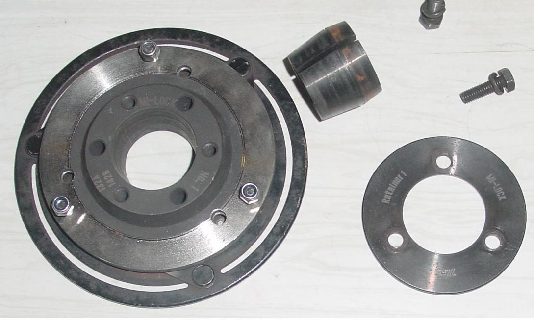
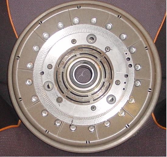
Hi to all I have use taperlock system with success. The product name I use is " mi-lock" around 25$ for the set for 25mm, plus whatever size pully you need to use. I just turned the shaft around, nothing to machine, except the way you want to fix the rotor to the pulley. I have run a timing pulley 1:1 connected to the propellor shaft of my boat and did some test changing direction of rotating, going from full forward to full reverse @ ~ 1000rpm without a problem. A few days ago I even made a rotor, rivited to a alu plate, and this plate bolted to a electro magnetic clutch. I used alu rivets with alu pins, that the rotor doesn't get cracks. cheers Harald 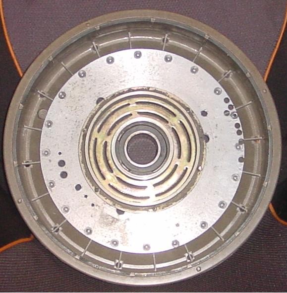
Hi Gordon Sorry to upset you with my pic. I am not a computer wizard and it took me some time just to work out how to crop and I wasn't able to save only the cropped part. I might just stay away from adding any pictures. cheers Harald PS: I know I could set the camera to smaller size, but mine works only on the max size, menue screen is broken. |
||||
| GWatPE Senior Member Joined: 01/09/2006 Location: AustraliaPosts: 2127 |
Harald, What is the point of posting huge pics. At least do a preview post. Not everyone has 24" monitor with 1920x?? resolution. This issue has come up many times. It really stuffs up the thread. Please EDIT your pics to a smaller size and resubmit. Hi dazz, Are you repairing a washing machine?... Gordon. become more energy aware |
||||
| dazz Regular Member Joined: 15/04/2008 Location: Posts: 78 |
Hey Gordon, Nah, just playing with the shaft and other bits to see how it all goes together and the different design aspects. I'm actually working on a heat engine to use wasted solar hot water. If you are heating a 160L tank with the standard 20 vac-tube system then you get all the heat you want in summer and about half in winter if you live in Tas. So I am working on a 100 tube system that completely heats the tank in winter and does some hydronic heating of the concrete pad. Of course, in summer your tank is heated in about an hour and you don't need the pad heated. so there is a lot of heat that is wasted(the system generates about 5Kw peak) So a heat engine converts the spare heat to mech power and then from mech to elec is where the F&P comes in. So far I have welded a cog on the free end of the shaft. But I haven't rewired the stator yet. So just trying to absorb as much info as I can from you guys so I know what they can do. Also, my house is on a large bush block so I'm thinking wind power later on to add to the mix :) |
||||
| brucedownunder2 Guru Joined: 14/09/2005 Location: AustraliaPosts: 1548 |
Hey Dazz,, Don't get too upset ol mate ,you've a very long way to go yet.. Sorry if I pissed you off ,honest. It was that Gordon guy ,he put me up to it !!! (He's me mate),or was !! Bad Bruce Bushboy |
||||
| Page 1 of 2 |
|||||
| The Back Shed's forum code is written, and hosted, in Australia. | © JAQ Software 2026 |
