Notice. New forum software under development. It's going to miss a few functions and look a bit ugly for a while, but I'm working on it full time now as the old forum was too unstable. Couple days, all good. If you notice any issues, please contact me.
Dinosaur Guru Joined: 12/08/2011 Location: AustraliaPosts: 357
Posted: 10:47pm 07 Apr 2019
Copy link to clipboard
Print this post
Hi All
Testing a "cape" for the Baglebone Black. It has 20 N Channel Fet's as outputs and 8 opto couplers as Inputs. The board is designed to handle about 20 Amps at 24 Vdc. So basically I can drive high current loads (Stepper motors etc) direct. The Fet's are STU85N3LH5. RDs of 0.005 ohm.
It all works well except at power up of the BBB, all the outputs go to 3.3vdc and thus turn all the 24 vdc outputs ON.
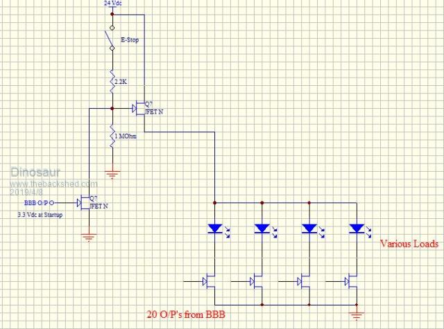
Anyway, decided on a new approach. Firstly an E-Stop decides if the outputs should be allowed ON. But people forget to reset the E-Stop, so not foolproof. OK, so lets use an output to enable the Supply voltage, however that output is already ON when you turn the power ON. That's when I dreamt up the circuit below.
Taking advantage of the fact that the outputs are at 3.3vdc , I use it to drive one Fet to pull the other one Off. As soon as the BBB has powered up, and I have initialised the outputs, the 24 VDC rail will be allowed through to the 20 O/P's.
My doubt (and that is why I am posting) is if all of the other 20 outputs are off, the voltage rail above the 20 outputs will sit at 24 vdc. In fact it will always sit at about 24 vdc.
Should the 1M Ohm resistor be connected to ground or the Source leg (Power rail to 20 o/p's) Will this circuit even work ? Problem with loading pdf and jpeg snipit not good resolution. Top R = 2.2K Lower R = 1 M Ohm Bottom Fet is driven by O/P.
Regards
Edited by Dinosaur 2019-04-09Regards Hervey Bay Qld.
wiseguy Guru Joined: 21/06/2018 Location: AustraliaPosts: 1296
Posted: 05:52am 08 Apr 2019
Copy link to clipboard
Print this post
Circuit seems ok to me at first glance and should work fine - you have used the issue against itself to effect a cure. I think to be more technically correct 1M resistor should go to ground not the FETs source. Otherwise with no loads there will be a voltage measured at the LEDs (sneak path through 1M resistor) that might be annoying. I like off to be OFF. If at first you dont succeed, I suggest you avoid sky diving.... Cheers Mike
Dinosaur Guru Joined: 12/08/2011 Location: AustraliaPosts: 357
Posted: 02:11am 12 Apr 2019
Copy link to clipboard
Print this post
Hi All
Am awaiting my board blanks to test the above question, but another "issue" has drawn my attention.
Up to about 20kHz the rise time is acceptable with only slight rounding at the top, however at 40 kHz the rounding becomes significant where eventually the peak voltage starts to suffer. The Fall time remains unaffected.
Not sure if I will ever need anything to be switched at that freq, but worth pursuing.
The Gate threshold voltage is specified between 1 to 2.5 v with 1.8v typical. The Beaglebone black has 3.3 vdc outputs, and so that is the max voltage I will get at the gate. There are no resistors between the cpu output and the gate. Turn On time is specified at 6-14 nSec.
My question: If I drive the gate at 5vdc, will that improve the rise time, and thus extend the usable freq.? Tried to find a mosfet with lower Gate threshold voltage , but current capacity then drops as well.
I can post a waveform if the explanation above is insufficient.
Regards
Regards Hervey Bay Qld.
tinyt Guru Joined: 12/11/2017 Location: United StatesPosts: 559
Posted: 12:16pm 12 Apr 2019
Copy link to clipboard
Print this post
How about changing the Startup FETN with an NPN bjt. I think they turn on at 0.6V. You have to add a series resistor between the base and the BBB O/P. Will probably need another resistor between the base and GND.Edited by tinyt 2019-04-13
Dinosaur Guru Joined: 12/08/2011 Location: AustraliaPosts: 357
Posted: 12:25am 03 May 2019
Copy link to clipboard
Print this post
Hi All
Just an update to my circuit above. tinyt I played around with some transistors I had (2N2222) but could not get the N Channel to to turn on fully. I think a lot has to do with the N Channel liking to sink the load in the Drain leg. All 20 of my outputs are in the Drain and deliver the full 24 vdc to the load. The best I could get was 22.3 vdc.
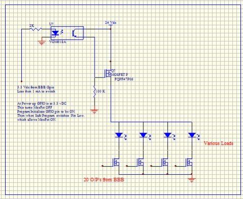
Anyhow after a lot of trial and error, I concluded that the P Channel is the ideal candidate because it likes to supply the load in the Drain leg. And that is the purpose of this, to supply power to all the loads.
I tried dozens of ways to drive the P channel with a N channel, bit in the end the opto was the best solution.
So for anyone else contemplating this the circuit below.
Regards
EDIT: The part numbers are: P-Channel FQPF47P06 , N Channel x 20 = GK1CL509, Opto VOM618AEdited by Dinosaur 2019-05-04Regards Hervey Bay Qld.