
|
|
Forum Index : Electronics : MosFet x 4
| Author | Message | ||||
Dinosaur Guru Joined: 12/08/2011 Location: AustraliaPosts: 357 |
Hi All Continuing on from my previous post on Isolated Converter , I have decided I am not happy with the time it takes to get from 80% to 100%. The system works perfectly but the current drops from 4.5A to 0.5A (around 85%) when there is 20A available from the Solar. The other reason for change is that the DDR-15 has a small pot that is very sensitive and am not looking forward to bouncing on 4WD tracks and finding my presets altered. So after seeing many circuits on using Mosfets as Voltage regulators, decided to purchase some from Amazon and will test the attached circuit. All of the circuits using the IRLZ44N are simple and the same, however, they all use potentiometers to set the voltage. I will use a Pot to find the resistor values and use them to get the fixed voltages. BUT, there are some dangers. Not using isolated converters, means that the voltage each cell gets is relative to the Battery negative. That means that if the cell before it is VERY low then the cell that gets 7.1v may actually result in a higher voltage until the low cell comes up As I am already monitoring each cell for a 3.6v limit (regardless of other cells) I will simply drop the control relay and wait for it to recover. My questions for the Mosfet guru's on the forum are: 1. If I drop my gate control positive voltage and thus pulling the gate to 0v, will that prevent any current on Source pin. 2. Considering that there are cells with higher voltages next door, what protection do I need to take to prevent reverse current flow. (Or is that not possible with MosFet's) 3. Functionally, considering that the cell's resistance to Battery Negative is about 0.2milli Ohm and the DRSON is 20milli Ohm, will the Mosfet stay ON and deliver higher currents until the voltages equalize.? 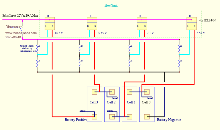 Edited 2025-08-10 19:53 by Dinosaur Regards Hervey Bay Qld. |
||||
| Solar Mike Guru Joined: 08/02/2015 Location: New ZealandPosts: 1216 |
Will try to answer a couple of your questions, others please chime in If not correct. 1: Turning gate control voltage off, all gates are at 0v or below referenced to the source's, so yes mosfets are off, any leakage will be in micro amps. 2: Don't think reverse current flow will be a problem. 3: Your mosfets will operate in their linear region, if you look at the SOA curve for these, there is none defined for DC operation, so these will most likely self destruct at any serious current into the battery cells. Their gate voltage will be very in-accurate as the PV voltage is not fixed; cannot see this scheme working to well. A high current inductive balancer would work > 10amps if you can get the impedance's low enough, but relatively complex. Easier to place a 10-15 amp load switched resistive across any cell runners when under charge, again more complex, but very accurate. Cheers Mike |
||||
| Dinosaur Guru Joined: 12/08/2011 Location: AustraliaPosts: 357 |
Hi All Thanks for your response Mike. I have literally watched dozens of Youtube videos using this concept for DC motor control using only a Pot and a resistor. What is not evident from these videos, is how much the voltage changes with a change of load. They generally use an unregulated power supply to do these tests, but it wouldn't vary as much as a solar input will. I will continue to experiment once the MosFets arrive but will add a Zener and a couple of resistors to throttle back the current when is goes over the Zener voltage.After that pwm may be an option from the Rpi. The load of a cell should not change much. I have measured internal cell resistance and it only varies by .2 or .3 milli ohm from 80% charge to 100% charge. Either way I have a couple of cells that are RS, so plenty to play with. I have to admit to being a total novice with MosFets, but "Nothing ventured, nothing gained". Edited 2025-08-12 14:10 by Dinosaur Regards Hervey Bay Qld. |
||||
| The Back Shed's forum code is written, and hosted, in Australia. | © JAQ Software 2026 |
