
|
|
Forum Index : Electronics : 16 - 32 Cell Balancer, BMS
| Author | Message | ||||
| Solar Mike Guru Joined: 08/02/2015 Location: New ZealandPosts: 1216 |
I have built a number of Lifepo4 and Lead Acid multi-cell battery balancers over the past several years, both passive and active types; they all work in various degrees, some better than others. Add to the mix accurate measurement of each cells voltage and the design gets more complicated. The passive types discharge a load resistor across any individual cell when its cell voltage goes above a high set point under charge, depending on the load resistor, quite a lot of heat can be generated, requiring a large heat sink and perhaps a fan. They do have the advantage that the load current is known and doesn't depend on the voltage difference between other cells. The active types using a large ferrite toroidal core with windings linked to each cell and synchronous current pulses work very well, however to get high load currents the circuit impedance must be in the mill-ohms region when cell voltage differences are low, reading the individual cell voltages is also tricky with all the voltage spikes. Under ideal conditions where cells are matched, balancing can be achieved with a couple of amps; cells I am using are re-cycled 100 - 400 AH and various ages - manufactures, so rather large load currents are required to keep "runner" cells in line. A passive balancer with a known load current works best here, this design is a modification of previous variants, where a mother board hosts individual cell module pcb's linked to each cell in the battery bank. A controller connects to one or two MB's allowing either 16 - 32 cell batteries. Cell boards each have their own cpu, here a very cheap Pixaxe 08M2LE and talk to the controller via opto-couplers for isolation. In the past I have used a form of PWM for cell communications, where the width of the pulse specifies the cell address and corresponding cell voltage in milli-volts, this is quite fast and should work ok on 32 cell banks. Here are the pcb's that will be sent off to be made in the next day or so, I will draw up the schematics when its all working and any bugs ironed out. Controller 100x100mm 4 layer: Can drive a couple of large DC relays for main contactor control and inverter pre-charge. 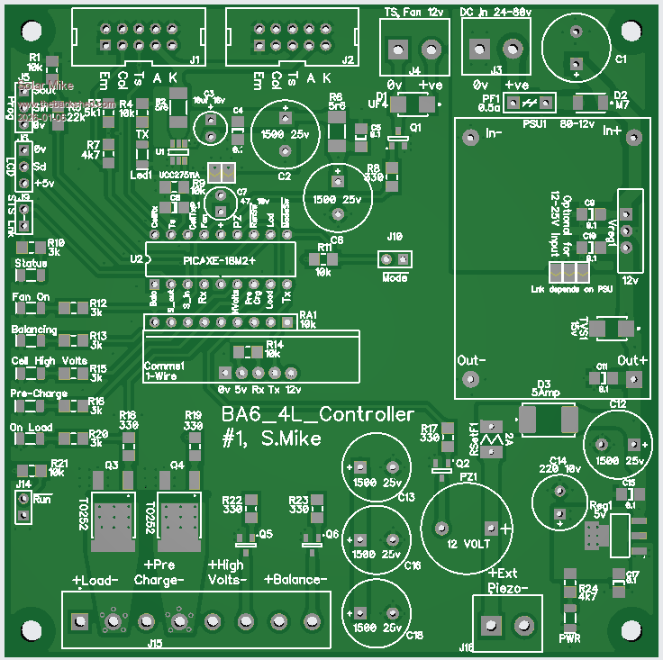 Cell Board 33 x 50mm: The 3.3v regulator is only used when monitoring 6V lead battery cells. 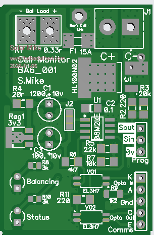 Mother Board 200x106mm: Large holes in the pcb are to allow air from a top mounted fan cool the 0.35r (10 amps) 50w resistors mounted below the main pcb, using a large alloy plate as heat sink. 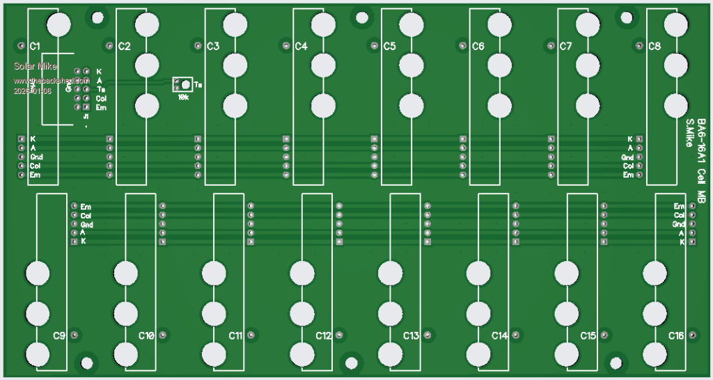 Cheers Mike Edited 2026-01-06 12:57 by Solar Mike Footnote added 2026-02-16 09:08 by Solar Mike Notes to self: Some of these batteries will be fully enclosed in a metal box, I have made no provision to read the cell temperature; not an absolute requirement, but would require a CPU with more pins, say 20M2, may implement in future. Mike |
||||
| Solar Mike Guru Joined: 08/02/2015 Location: New ZealandPosts: 1216 |
The 1-Wire communications setup may be of interest, it is based on a 12v logic "wired OR" system, having a large hysteresis to get noise levels down. The Master device supplies 12V,0v power to the slaves, with data isolation by opto - couplers. 2 way control bus floats at 12v when not active. Schematic: 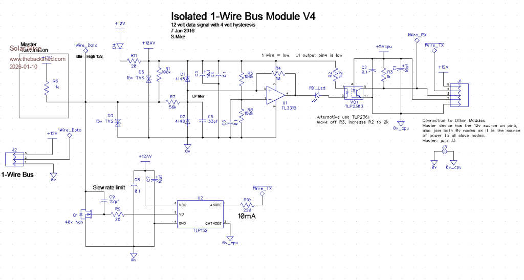 PCB 33 x 40mm: 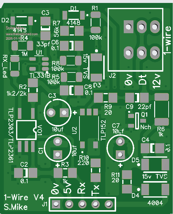 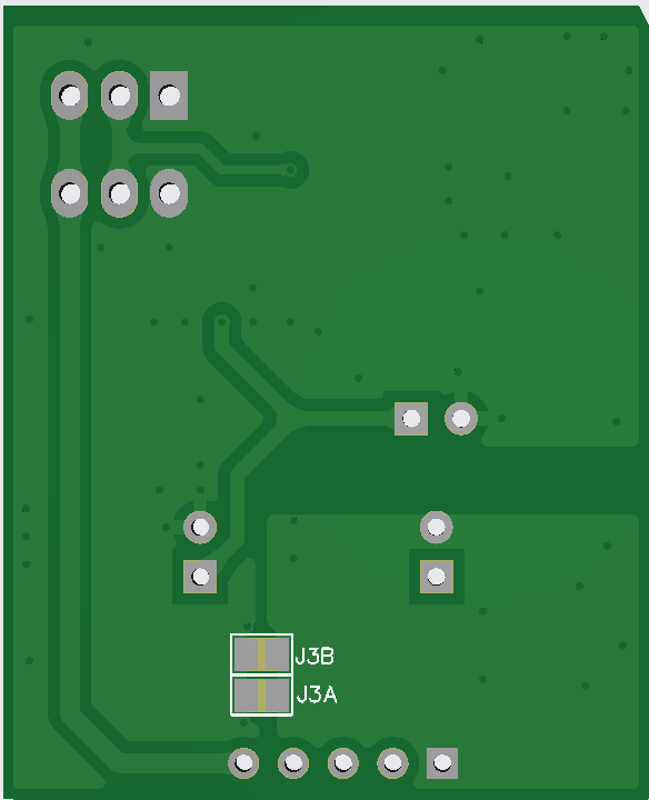 Gerbers: 6 pcbs fit on a 100x100mm board, I get them made 1.2mm thick and cut with a very large tin snips 1WireV4Gerbers.zip Cheers Mike Edited 2026-01-10 20:56 by Solar Mike |
||||
| Solar Mike Guru Joined: 08/02/2015 Location: New ZealandPosts: 1216 |
To initially set the balancer up, in the past, I have used a pcb with 16 series W.Wound resistors each with a capacitor, all powered from a current limited PSU. This simulates a 16 cell battery and is easier to manage on the bench rather than connecting to a live battery bank. Was a bit messy, so have decided to use a new board using accurate 0.1% 1 watt resistors and a small cooling fan. The current is just over 100mA and provides a reasonably accurate cell voltage that can be easily varied by the PSU for testing. Here is the design for that, 100x100: 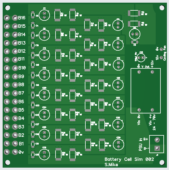 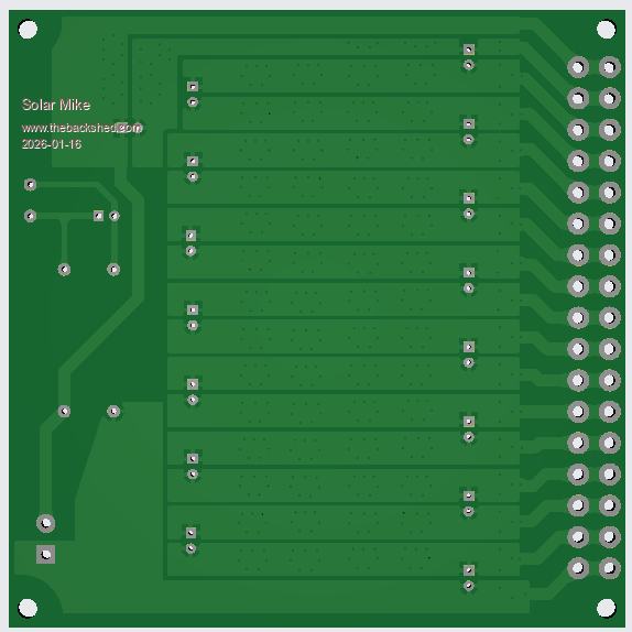 Fan PCB, sits above the main board: 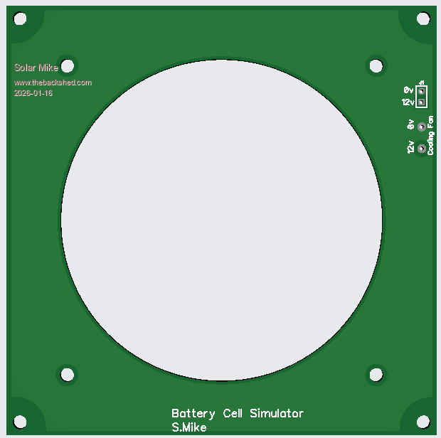 Cheers Mike Edited 2026-01-16 16:43 by Solar Mike |
||||
| Godoh Guru Joined: 26/09/2020 Location: AustraliaPosts: 667 |
Wow Mike that is a lot of work! I haven't got to the stage of using Lithium batteries at home yet. I may look at them when the VRLA batteries I have now die , but I am hoping that that won't be for quite a while. It is amazing how much work you put into these projects, it will be interesting to see how it turns out Pete |
||||
| Solar Mike Guru Joined: 08/02/2015 Location: New ZealandPosts: 1216 |
I guess, prob about 24 hrs to do those pcbs, so not too much, and now that I have retired, I don't get paid for it.... I have been using a different sort of balancer for our 3 banks of 300AH 48v Lead Carbon 6v cells, so 8 cells in series per bank; will post the pcb below. That system uses a flying 1uf capacitor that gets switched across each cell in the bank via DPST optomos relays, type AT224, the cap is then isolated from the bank and switched to an ADC input of the CPU, measured, then discharged, cycle repeats for next cell. Any balance loads that maybe on at the time are switched off during the voltage measurement phase to prevent voltage drops on the balance wires. Takes about 1 sec to scan all 8 cells in the battery; system works pretty well but would be a bit slow if expanded to 16 or 32 cell Lifepo4 banks, thus the new design. The cell loads are power resistors screwed to a large heatsink, mosfet switches driven by an opto to voltage isolator chip TLP3906. The new design will be much faster and cheaper to build, as the cpu's are about $2 each and other opto components not required. Here is the older balancer PCB, as its serial driven, extra boards can be daisy chained for more cells as required: 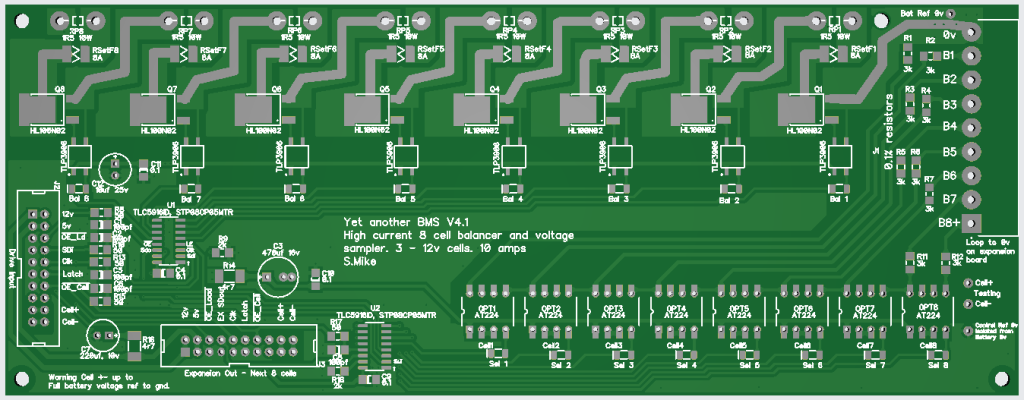 And it's controller: 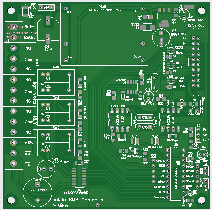 Cheers Mike |
||||
| nickskethisniks Guru Joined: 17/10/2017 Location: BelgiumPosts: 477 |
Nice project! Do you implement a software calibration per cell, or are you happy with the accuracy? I have made a simular project for my mb31 cells, its build arround an esp32 main controller board and the cell boards use atmega 328 mcu's. They communicate over uart bus isolated by opto can tranceivers0. Works really well, but best result is when cell voltages were calibrated, the 10bit internal dac is a bit on the low side, I use 0.1% resistors and an external 0.1% reference ic. I'm working on an stm32 based version wich has an internal 12 bit dac, I aim for a 1mV resolution. |
||||
| Solar Mike Guru Joined: 08/02/2015 Location: New ZealandPosts: 1216 |
The "flying capacitor" system uses 0.1% resistors and 1 common ADC input. I calibrated in software using a fluke meter and known PSU in place of a cell. If its within 10mV thats ok by me, as balancing is only occurring above 3.5V per cell so well into the voltage rise part of the curve. The individual 08M2 chips are using same 0.1% resistor divider and internal 2.048 reference, they seem to be reasonably close in accuracy, so no extra calibration required. I am not too worried with absolute 1mV deviation, the cells only spend a short period being balanced by the resistive loads, before system switches to a lower "Float" voltage. Way I look at it is as long as all cells are within 20-30mV deviation then they are balanced, at the top end of their voltage end point. I did look at using a voltage ref IC for auto calibration, but the Picaxe Basic being integer based and limited to 16bit maths make it too difficult software wise; your use of atmega 328 mcu's would work much better. |
||||
| Solar Mike Guru Joined: 08/02/2015 Location: New ZealandPosts: 1216 |
Have started building up the pcbs for the balancer, have the controller and a couple of the cell monitor slaves built; will test out and write some software to make sure all is working, then make the remaining 14 slave modules. What I really need is a SSR relay, with an inbuilt current shut-down, this can be connected to the BMS Load output and act as a main Load relay to the inverter supply input, combined with a simple resistive pre-charge function. The over current setting would have a pot to set between low and high limits for various testing purposes. If I bolt a number of TO-247 mosfets to copper bus-bars, then using a differential gain amp to measure the voltage drop from each end of a bus-bar, I can get a current reference for input to a comparator. In the past I have used GigaVac relays as the power isolation to loads on the battery, it now seems easier to make a solid state version combined with the current sensing. Here is a conceptual drawing of what I want to make, ideas please from anyone else... 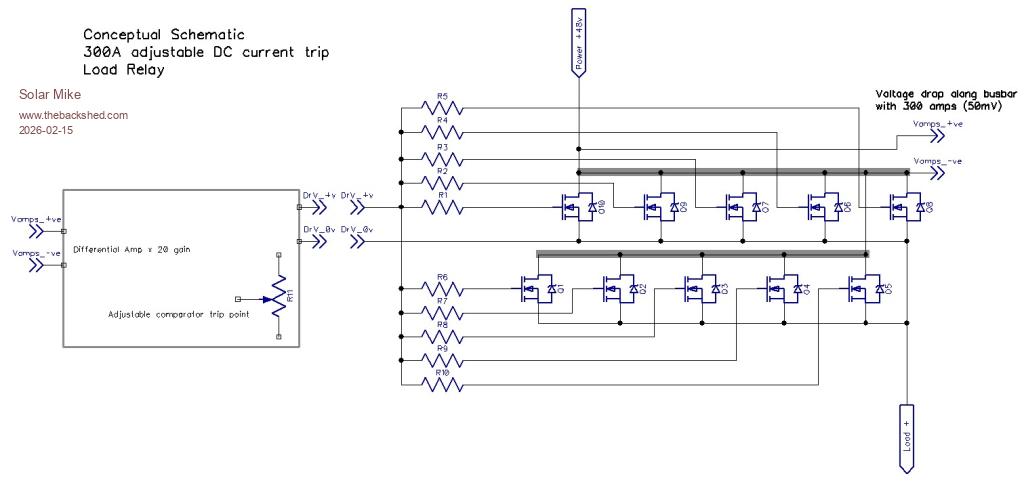 You can go out and purchase a 48v BMS with 200-300 amp functionality, and they are not that expensive, however having seen a number that have self destructed causing fires, I don't have a lot of faith in the commercial products, prefer something that's also repairable. Mike Edited 2026-02-15 12:59 by Solar Mike |
||||
| Solar Mike Guru Joined: 08/02/2015 Location: New ZealandPosts: 1216 |
Software written for the BMS, have it working on a Master and 2 slaves, need to go and get a sheet of 2mm thick aluminum and assemble all 16 slaves + 0.36R load resistors, so I can test out on a small 180AH 16 cell battery currently putting together. For the 300A SSR relay, have scrapped the idea of measuring the load current across the busbars as the loads are not even along the length due to the mosfet connections. Could measure the voltage drop across all paralleled mosfets, combined 0.15 mR, but this changes with temperature and isn't consistent. Instead have opted to use an isolated current sense ACS723,40U in the source of the last mosfet, as all mosfets are tightly thermally connected by being bolted to an alloy bar 50 x 3 mm, they will all tend to current share; so whatever current is flowing in the sense mosfet will be proportional to their combined total. This will allow a max of 400 amps to be sensed with little extra heat. Here is a conceptual schematic: 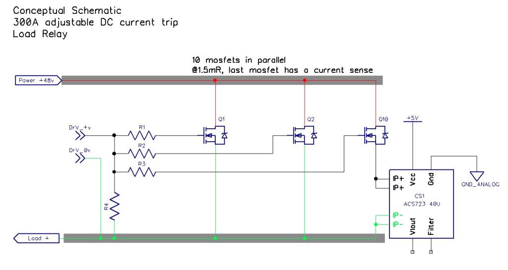 Cheers Mike |
||||
| Solar Mike Guru Joined: 08/02/2015 Location: New ZealandPosts: 1216 |
Continuing with this project, have completed a layout for the high current inverter load switch. The objective was to enable the BMS to disconnect any high power loads from the battery, should there be an over\under voltage event or excessive current draw. The current BMS design doesn't have any facility to measure load current, I could have used a high power shunt of some sort or a pass through magnetic field detecting device connected up to a balanced input comparator; in the end I decided to make this more modular and incorporate the current detection into the load switch. This version of the load switch uses 10 mosfets in parallel, one of which senses load current; theory being they will all somewhat current share as they are bolted to a 5mm thick piece of aluminum busbar and will be in thermal equilibrium with each other; the load current will be 10 x the sensed current... hopefully. I was going to make the circuitry all analogue - No CPU - but that would have made things more complicated, so opted for a simple CPU to give following functionality. Pre-charge the load (Inverter Caps) for a time and switching to full load when the load voltage comes up to the source battery voltage. Some led's that show running state. A comparator with setup pot to detect an over current, causing CPU interrupt to turn things off. As the CPU knows the Load and Source Input voltages along with the sensed current, you could use this board as a very simple stand alone system, if individual cell voltages were not a concern. The mosfets bolt onto 50mm wide busbars that extend off the LHS of the pcb, small solder lugs solder to the source pins for bolting to the "Source" busbar. The drain can use busbars bolted to top\bottom of the pcb, this presents extra current capacity and surface area for cooling; if max current is 40A in the sense mosfet, then 400 amps doesn't sound unreasonable for a current limitation. I have pulled apart a few 200A commercial BMS units that had self destructed, catching themselves and the interior battery case on fire, was not pretty.... they used 30 or more surface mounted mosfets in parallel groups connected by several 5mm round copper rods soldered to the pcb tracks; approx 40mm^2, 200A no way. Hopefully this design might be more robust and repairable. Schematics: 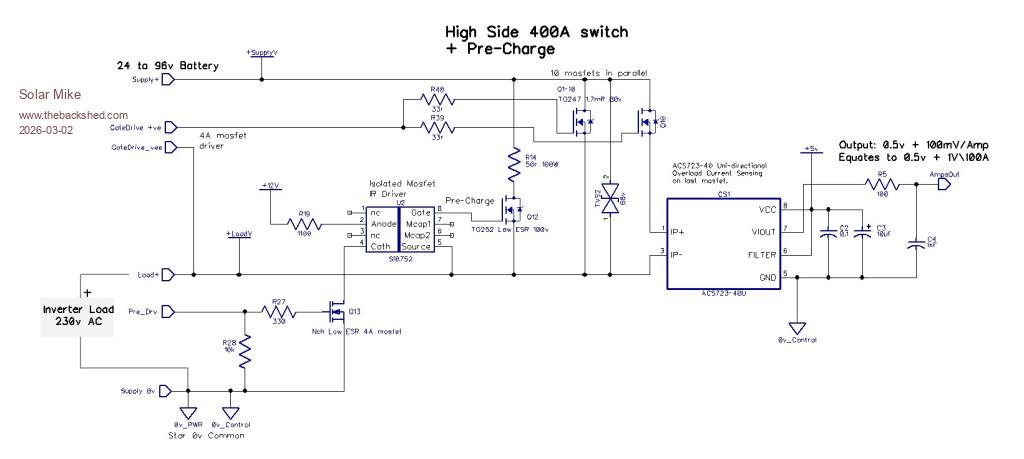 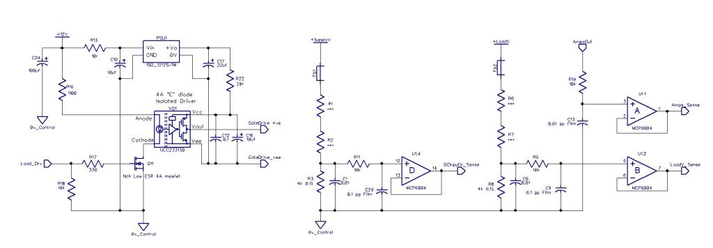 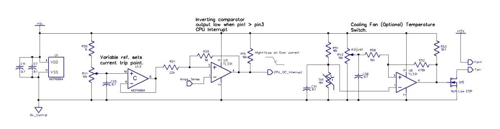 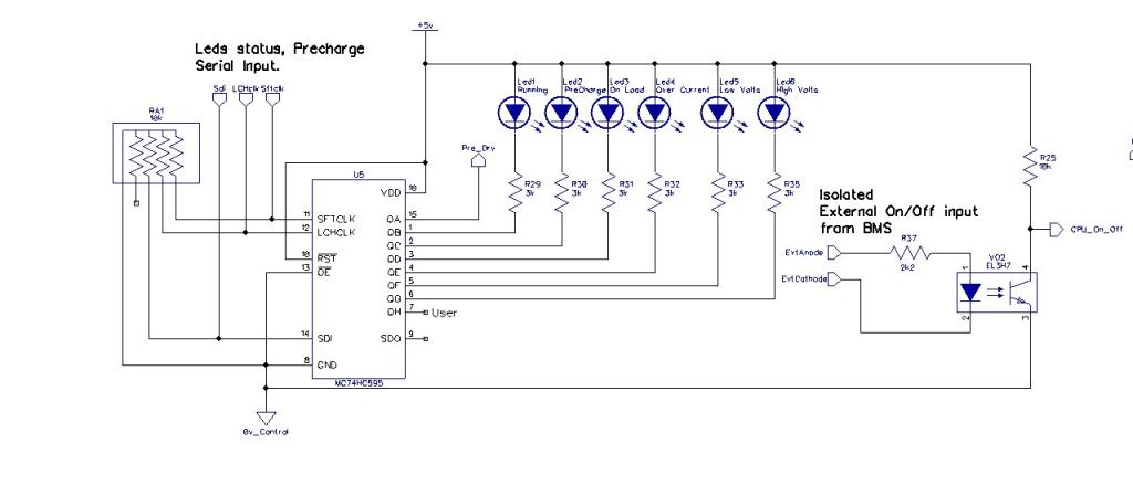 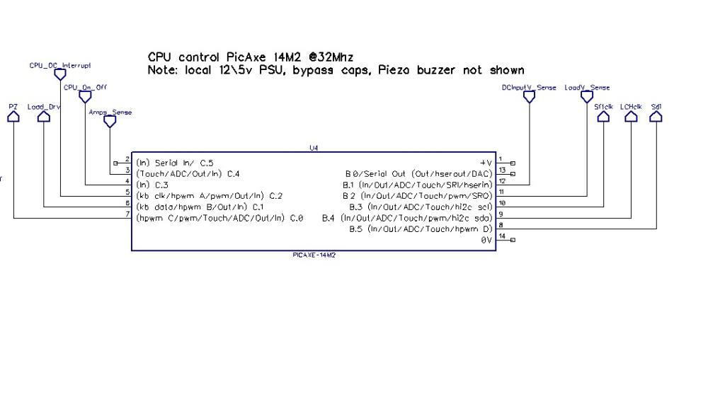 Main PCB 251 x 166mm, 2 layer 1oz copper: 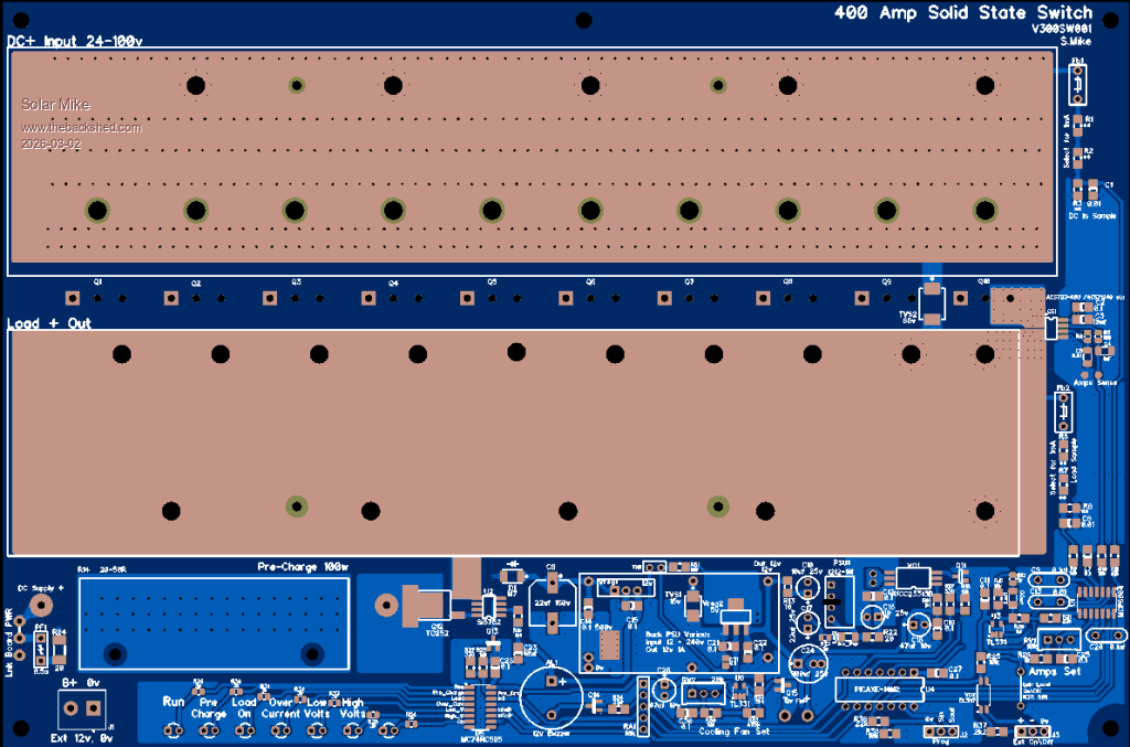 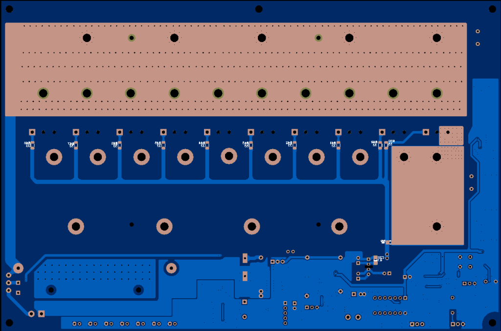 Edit: Schematic V300SW.pdf Once I get this all working, will post some gerbers and software. Then next mission is to purchase a 3D printer and have a go at making a small box to put it in, I have lots of projects on the go and can never get decent box's to fit them in, so its time to get Fusion 360 software and make a start. Cheers Mike Edited 2026-03-02 16:48 by Solar Mike |
||||
| analog8484 Senior Member Joined: 11/11/2021 Location: United StatesPosts: 203 |
That's an interesting 400A design build approach. Have you ever done it for that level of current before? I also have had issues with a couple 200A BMS units and find the designs marginal at best. Look forward to seeing your 400A unit in action. |
||||
| Solar Mike Guru Joined: 08/02/2015 Location: New ZealandPosts: 1216 |
Not at that level no, each 50 x 5mm busbar has 0.022 mR resistance if I use 50 x 3mm its 0.037 mR, either case the heat loss is minimal. The mosfets have 24 watts loss over 10 devices @400 amps, max current I will ever see is 300A for brief periods, it should survive. Mike |
||||
| Solar Mike Guru Joined: 08/02/2015 Location: New ZealandPosts: 1216 |
More progress, the high current switch pcb's arrived today, so will make up a board and do some tests over the next week or so. Back to the original topic, I have made up the 16 small cpu based cell modules that fit atop the main carrier board. 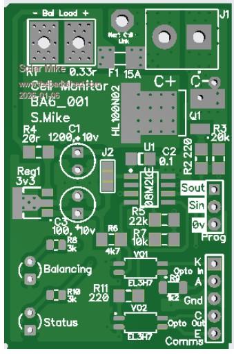 Have been waiting for replacement right angle 2 pin connectors to arrive, originally made the modules for straight connectors... and after fitting a couple for testing, you cannot do up the socket screws, bugger! (Kiwi Expression); anyway have made them up now with the new connectors. These little pcbs take forever to build and I need another 64 for this project, so I think a re-design maybe is in order (new topic pending). Will get this lot going, software is almost completed, well it works 100% with 2 modules, and use it on my small battery bank for the EV charger. Host board: 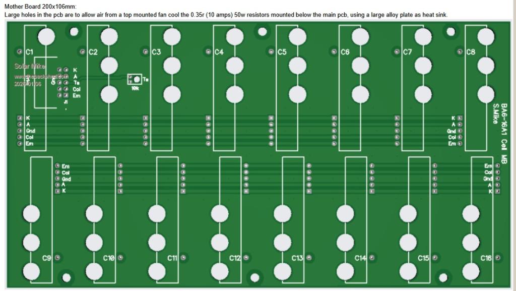 The vertical pcbs soldered to the main board with RT angle pins, don't have room to screw up the terminals. Cheers Mike |
||||
| Solar Mike Guru Joined: 08/02/2015 Location: New ZealandPosts: 1216 |
Ready to test this out, just have to finish making up a new steel framed battery rack with some wheels, so I can easily move it. Have also got another set of Lifepo4 cells ex EV car, not sure what state they are in, measured a few and seem to be about 85AH, I need to make a rack for these also and do some testing. I intend to test out a different sort of balancer on these as I want to put them in a small case + balancer + PV charger + LF inverter; not wanting to have too much heat generated by the dissipative balancer resistors, have decided to try out an alternative active balancer setup, similar to a previous project last year. That previous balancer used multiple forward converters sharing a single ferrite core, one converter per cell, it worked, but with 16 cells started to get a little messy. The large gaps between cell windings on the core did not have enough coupling, too much leakage inductance, creating an inefficient spiky waveform. So have flipped the design around and gone for a central two switch forward converter powered by the bank voltage 56 volts at balance point, with each cell coupled to the core using a synchronous rectifier. This is similar concept to the design that Warpspeed produced awhile ago. This new design uses a two mosfet switch forward converter, as this have some advantages over a single switch method; no reset winding is required and less stress on the mosfet switches, disadvantage being it has more components, cost however is similar. The main primary core has 16 x the number of turns of the secondary cell cores, thus each secondary sees 1/16 of the average bank voltage, high cells (the bank) will place extra charge into lower ones. Some schematics: Forward Converter: Have used "E Diode" opto couplers to drive the 2 mosfets, as this allows good electrical isolation especially with all the RFI generated. 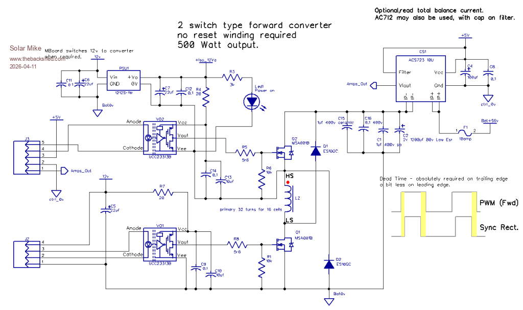 Cell Synchronous Rectifiers: Near identical to Warpspeeds circuit, have used more modern mosfet drivers that have a under voltage lockout UVLO of 4.5v, so will work with the lower supply voltage generated when the main core switches off: 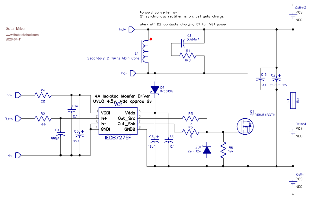 Synchronous Timing Generator: The PWM waveform from the CPU goes into this little module, trim pots allow setting the leading and trailing edge dead-times. 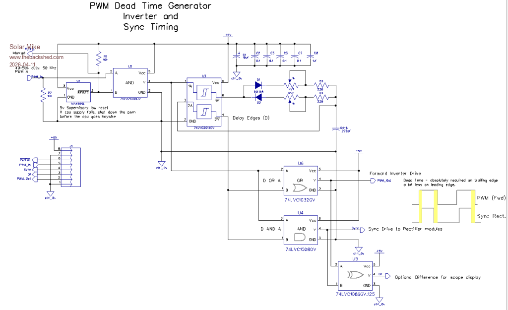 Each of the above go on there own separate PCB's and plug into the main motherboard PCB hosting the 16 rectifier modules and ancillary CPU. I have done it this way to keep the individual high current switching contained separated, thus allowing Star grounding of common the 0v rail. More to come... Footnote added 2026-04-11 21:16 by Solar Mike Schematic comments for sync rectifier are wrong, ref parts value have altered. should say: forward converter on Q1 synchronous rectifier is on, cell gets charge: when off D1 conducts charging C5/6 for V01 power supply. |
||||
| Solar Mike Guru Joined: 08/02/2015 Location: New ZealandPosts: 1216 |
Here is the synchronous rectifier board, 6 of these fit on a 100x100mm pcb The boards push into slots in the host motherboard and solder directly. The mosfet driver provides full isolation between input and output. 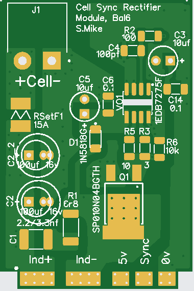 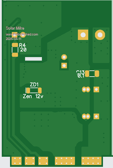 Dead-time generator is just a delay with adjustable times on leading and trailing edges of the PWM, prob be around the 100-200 nSec, will setup using a scope. Board has right angle header pins, push fit into a socket. The forward converter should be good for approx 400-500w without over heating, the 110v mosfets used have a 0.002R on resistance, perhaps a little more @6-7 volts. The main motherboard has 30 amp right angle pcb terminals with 4mm bolts for attaching the pcb vertically. Both forward converter and DT generator are on same 100 x 89mm pcb, cut with large tin snips. 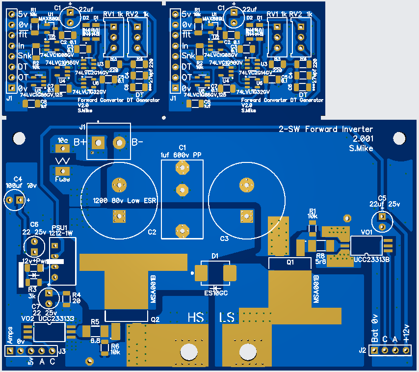 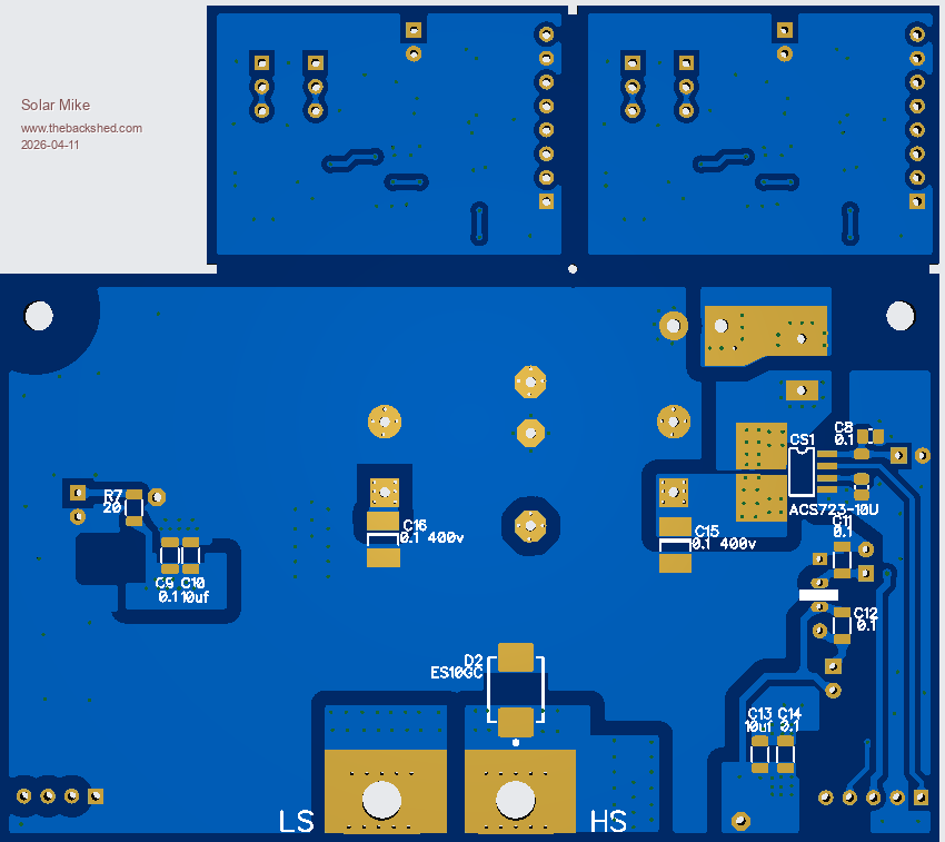 Motherboard, 178x152mm, 16 rectifier modules set in slots, solder blobbed connections arranged radially around the large ferrite core. I haven't made a schematic for this yet and probably wont until fully built and sorted. The terminal connector at the bottom has an opto-isolated input for external ON\Off control and a local test switch + an output relay possibly for "Balancing" status. 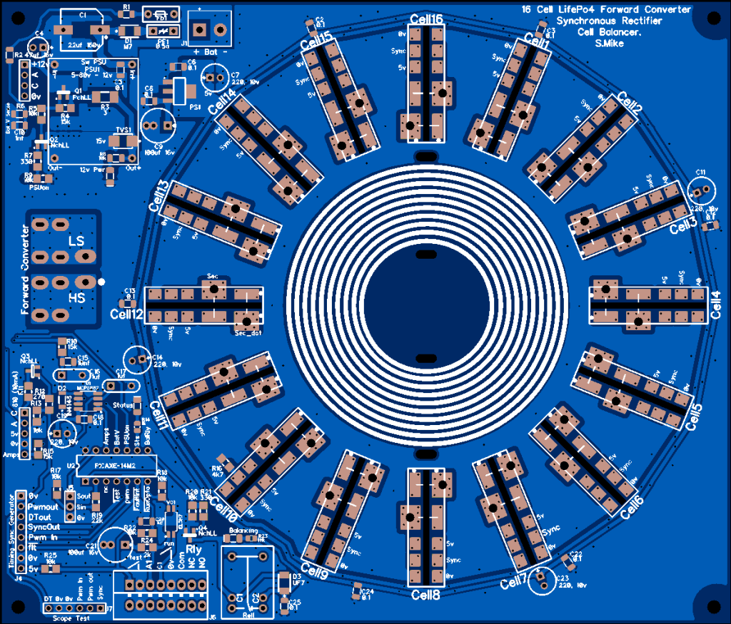 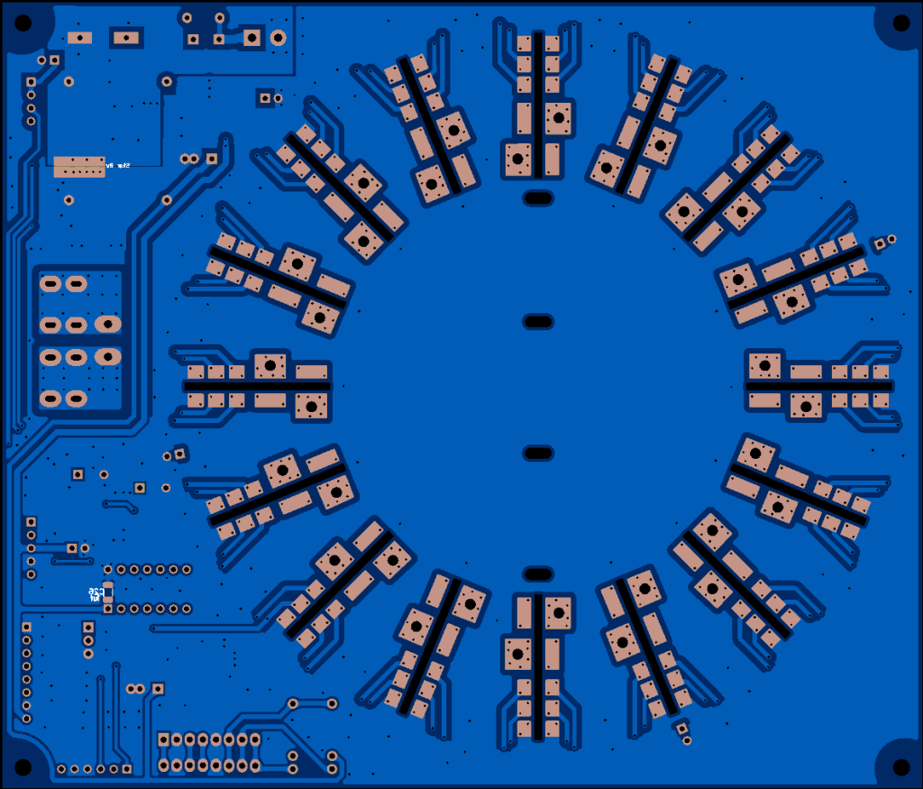 Will do some more checking, then send these off to be made. Edited 2026-04-12 08:42 by Solar Mike |
||||
| The Back Shed's forum code is written, and hosted, in Australia. | © JAQ Software 2026 |
