Home
JAQForum Ver 24.01
Log In or Join  
Active Topics
Local Time 09:23 20 Aug 2026 Privacy Policy
Jump to

Notice. New forum software under development. It's going to miss a few functions and look a bit ugly for a while, but I'm working on it full time now as the old forum was too unstable. Couple days, all good. If you notice any issues, please contact me.

Forum Index : Electronics : Fronius Internals

Author Message
wiseguy

Guru

Joined: 21/06/2018
Location: Australia
Posts: 1304
Posted: 02:39pm 12 Aug 2026
Copy link to clipboard 
Print this post

If anyone has any information or experience with Fronius inverters feel free to add to this post.

I have always wondered what chokes are in a Fronius inverter, I expected something special and hoped I would find a few toroidal sendust type cores. So finally I inherited a Fronius Primo 5kW single phase inverter. It is relatively easy to get a cheap Fronius from 0 - $50 reasonably regularly on marketplace.

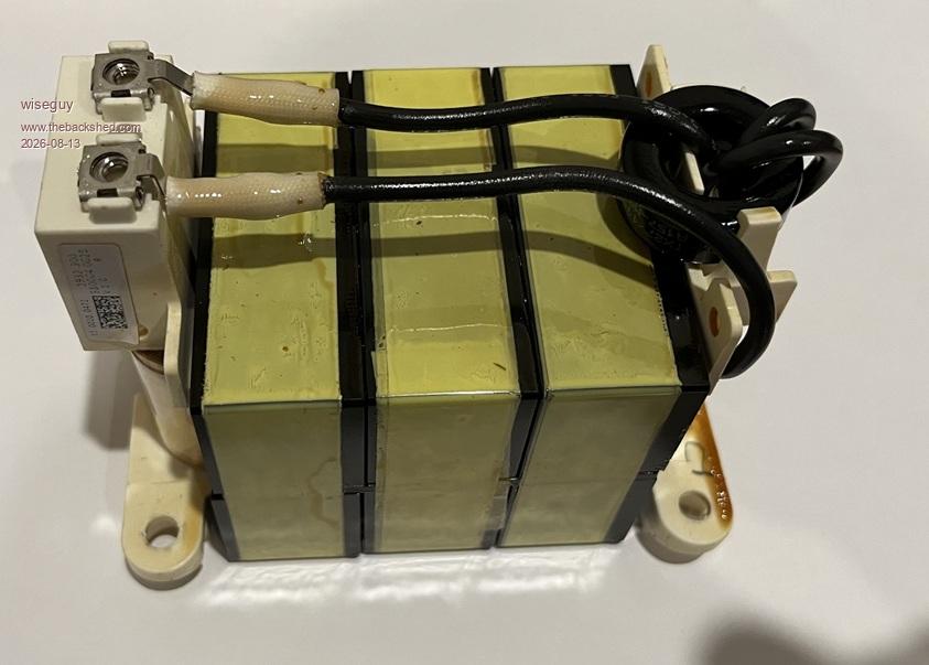
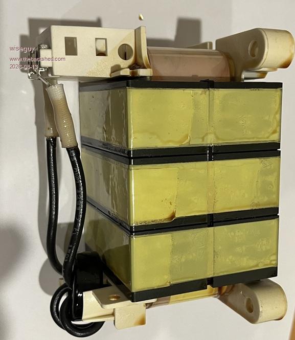
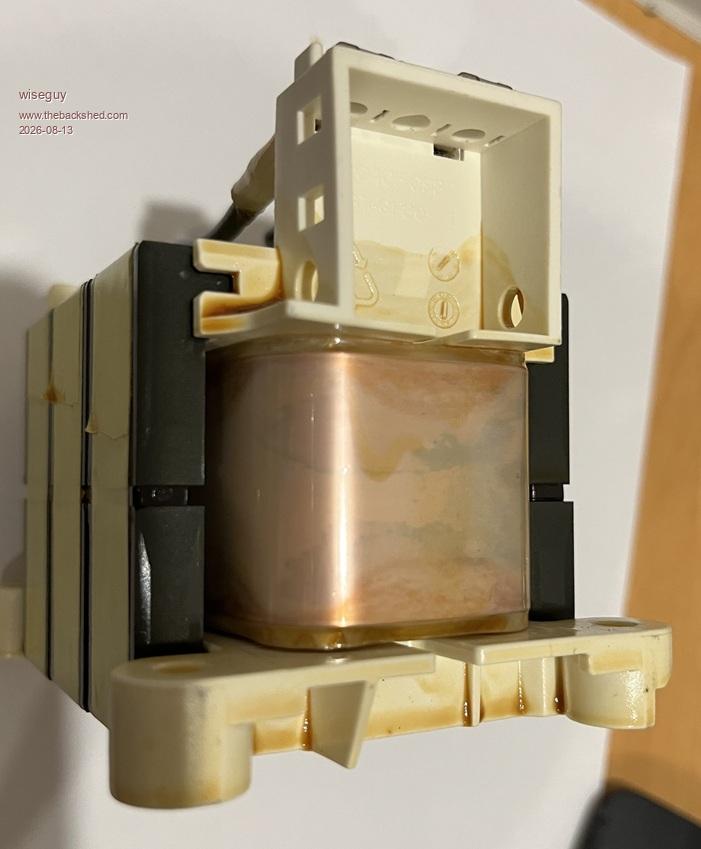
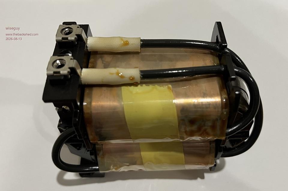
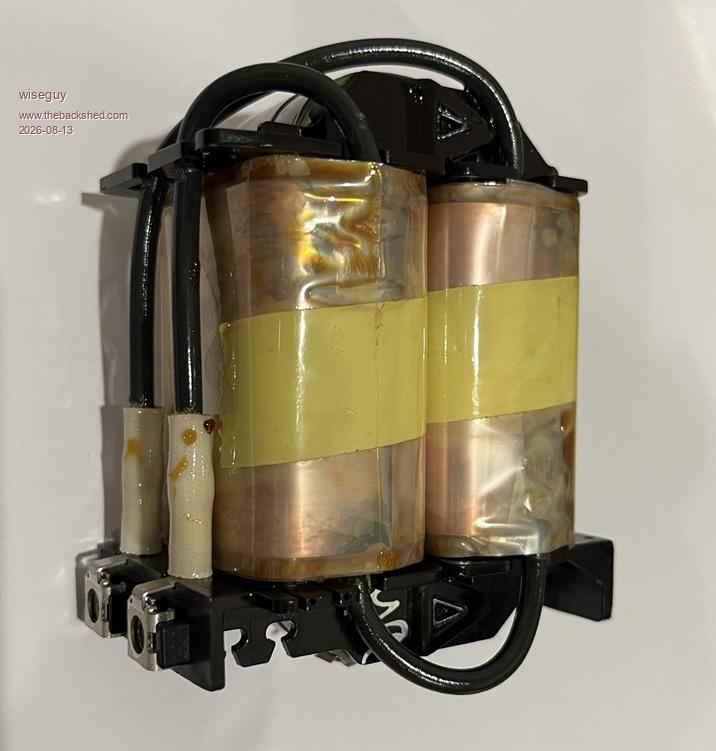
So I went a bit crazy and within ~ 30 minutes had undone about 50 screws and found the inductor "stuff" hiding under the main circuit board. There were 4 inductors in total two were made up of 3 stacked 60/65mm gapped Ferrite Ecores. The other 2 were the double "C" core inductors. All 4 inductors were wound with copper foil sheet in lieu of copper wires. the triple stacked inductor was ~ 1.6kG the double C core types were ~ 850g. I put the triple stack on the inductor tester which gave me a value of ~ 800uH. To double check I had also removed a 4u7 mains capacitor so I calculated that in parallel with the inductor resonance should be ~ 2595Hz.

Next put the parallel inductor/capacitor in series with a 470R connect the CRO across the coil/cap and wind up the freq generator & sure enough a strong resonance peak at~ 2610Hz - close enough.  I had not tested the second inductor on the saturation tester yet but out of curiosity I added the 4.7u cap across it and ran a sweep of the signal generator again and voila a resonance peak within 5Hz of the other inductor so its value is also 800uH.

So my first instinct is that these chokes are as useless as tits on a bull as the saying goes. The 4 inductor assemblies are all dipped and probably vacuum varnished, so unwinding the foil windings would be a miserable exercise. I think the triple stacked Ecores are a lost cause but I wondered about the dual C core. As there is a wire joining the two halves in series I considered what if we cut that wire and extend them up to the normal terminations so we end up with two foil windings in parallel.

I could only squeeze 6 measly turns on the minute remaining C core gap, which measured ~ 13.8uH yielding an Al of 0.39uH. That means the 800uH is from the square root of 800/0.39 or ~ 46T, so each half has ~ 23T that alone equates to ~ 200uH. If we parallel the two halves, because they are on the same core it will still be 200uH but can now handle double the current or at least run a lot cooler for the same current.

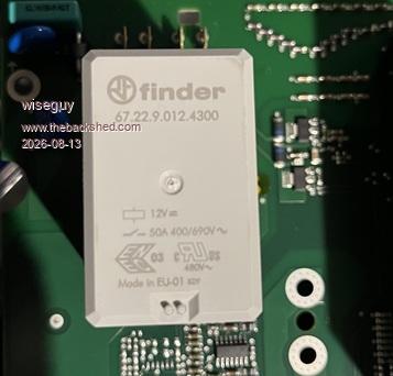
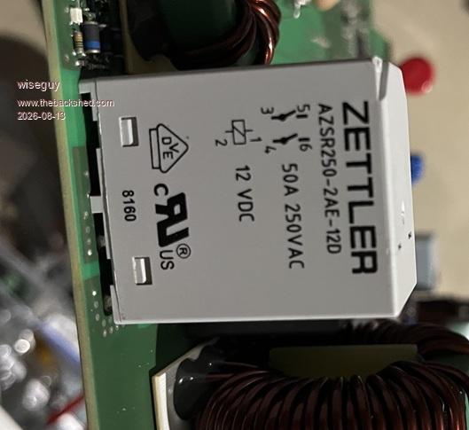
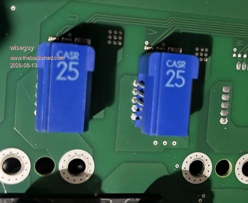
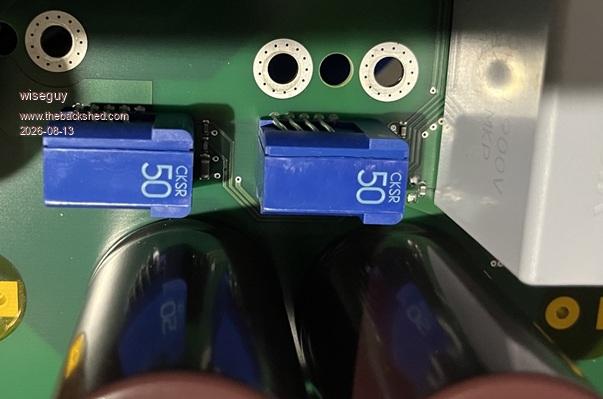
Assuming 54V out, to get 45A from that inductor with Vin max at 120V we need to run the MPPT at 8kHz, at 90V in 45A out we need to run at 6kHz, neither of these figures are encouraging so I don't see either of them as being much use. The inductors would be very audible at these frequencies.  The only other internal parts of possible interest were 8 x 510V 820uF Nichicons, 2 x 25A hall sensors, 2 x 50A hall sensors, a 12V coil DPST 50A 250V Zettler relay and a 12V coil DPST 50A 690VAC Finder relay.

Can anyone else see any practical (or impractical) use for these ex Fronius inductors ??

I think it is a safe bet that a 10kW Fronius probably just has more or larger of these inductor types inside?  Now you dont have to wonder what's in one. Oh and if you are thinking of getting lots of the FET/IGBT devices forget it they are a hybrid module with about 20 connections that would be hard to use in anything, I might post a picture of them tomorrow FYI


Edited 2026-08-13 00:55 by wiseguy
If at first you dont succeed, I suggest you avoid sky diving....
Cheers Mike
 
Godoh
Guru

Joined: 26/09/2020
Location: Australia
Posts: 697
Posted: 10:00pm 12 Aug 2026
Copy link to clipboard 
Print this post

HI Mike, seems that they don't have many useful parts inside. I have 3 Zeversolar inverters. I use two of them for backfeeding and one is a spare. They don't seem to have much inside worth trashing them for either. They do have relays that I bought some spares of, hoping not to have to change them but having spares in case will keep my system going longer.
pete
 
Revlac

Guru

Joined: 31/12/2016
Location: Australia
Posts: 1300
Posted: 10:46pm 12 Aug 2026
Copy link to clipboard 
Print this post

Thanks for spending the time to take it apart and show us the innards , the dual C core looks to be a bit bigger than the 5Kw Aurora, The choke as is tested 517uH I cut the wire between the 2 halves, One coil measures 157uH, its been working great, shame those Fronius aren't up to the task.
Cheers Aaron
Off The Grid
 
mab1
Senior Member

Joined: 10/02/2015
Location: United Kingdom
Posts: 286
Posted: 10:56pm 12 Aug 2026
Copy link to clipboard 
Print this post

If you're wanting sendust rings i did find some in a Solis g.t.inverter (~3.6kw iirc) during my wiseguy inverter build - so if you can find any of those local to you they would be a good bet:-
mab1s wiseguy inverter build
Edited 2026-08-13 08:58 by mab1
 
wiseguy

Guru

Joined: 21/06/2018
Location: Australia
Posts: 1304
Posted: 02:55am 13 Aug 2026
Copy link to clipboard 
Print this post

Mab, Thanks for the heads up I will keep my eyes open.

Pete the relays in theory can handle 100A if the contacts are paralleled - although we were usually advised against doing that. I also agree that the propensity to failure is usually cancelled out by having a spare on hand.

Modern inverters when ratted are a small pile of useful stuff and a large pile of junk to be thrown out. It reminds me a bit of a cooked chook.....

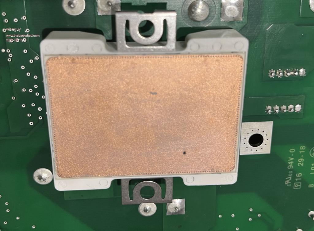
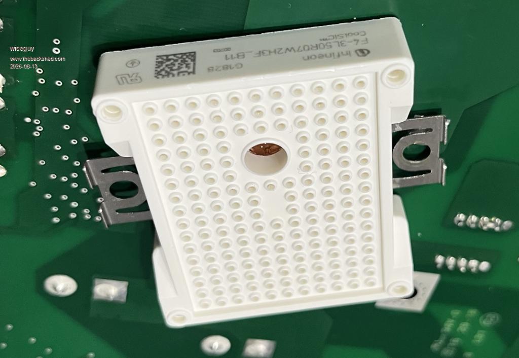
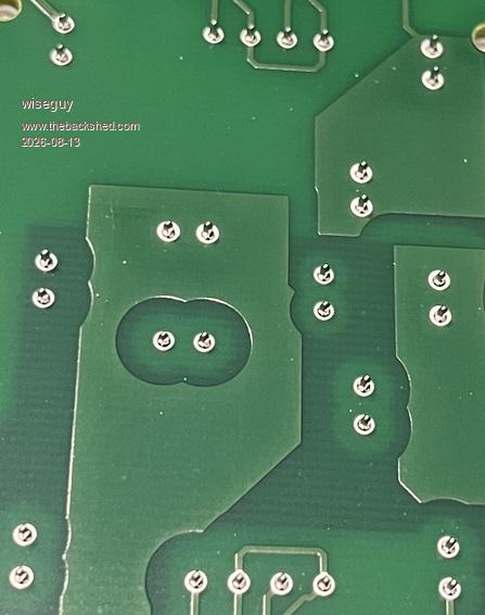
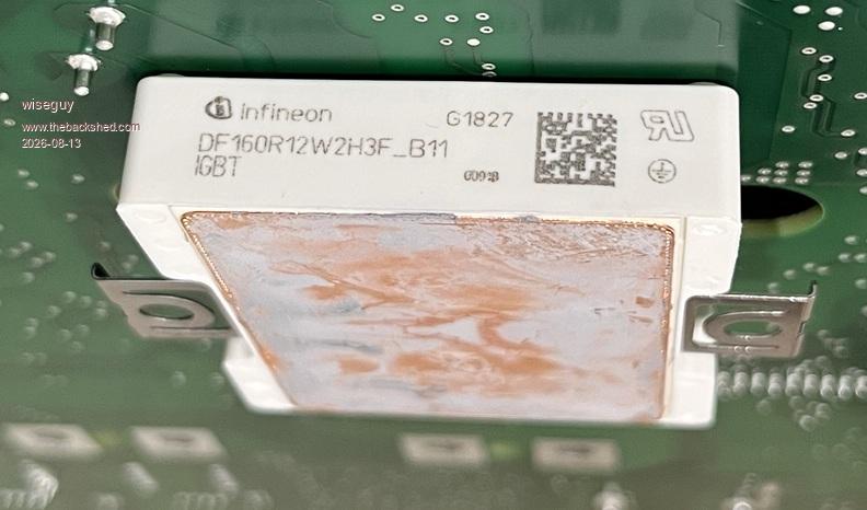
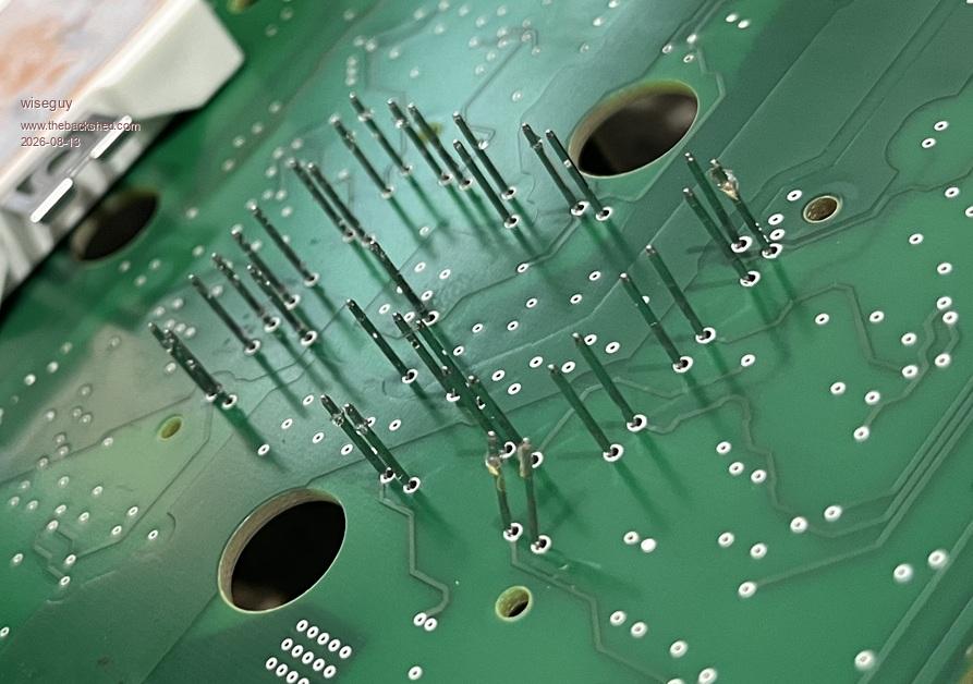
So now to the 2 IGBT/Silicon magic modules. I noticed they were press fitted into the board, no soldering so obviously removal should not be difficult. Starts prying with a trusty screwdriver, hear groaning creaking noises as module tilts a little keep prying around the perimeter voila module is free. The bad news is that all the pins are still firmly embedded in the PCB hmmm.

So search for data on the module, did not find data but found a 46 page booklet on using Siemens press fit modules - of course I should have read that first! Near the end of the booklet it advises for removal to press the pins all at once with special tools jigs and presses which of course we all have in the workshop.

It appears they insert the pins in the module then put in a special gel, heated to run easily to hermetically seal the pins. In theory if I could be bothered I could reinsert 30 /34 pins heat the module to reseal and if I had a datasheet on what the pins and internals do the pins could be soldered in a new board design of what?? They do advise that once pressed out they should never be repressed again but soldered. Yay this is some progress. The two modules have different part numbers and 30/34 pins.


Edited 2026-08-13 13:07 by wiseguy
If at first you dont succeed, I suggest you avoid sky diving....
Cheers Mike
 
Print this page


To reply to this topic, you need to log in.

The Back Shed's forum code is written, and hosted, in Australia.
© JAQ Software 2026