Notice. New forum software under development. It's going to miss a few functions and look a bit ugly for a while, but I'm working on it full time now as the old forum was too unstable. Couple days, all good. If you notice any issues, please contact me.
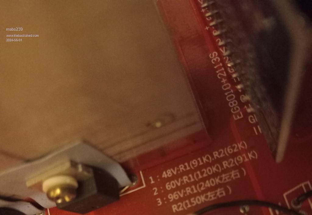
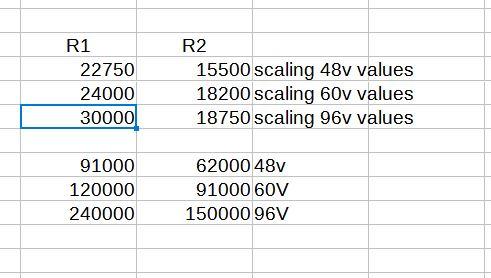
I have egs002 based inverter board. It specifies resistor values for 48V, 60V and 96V. I want to change it to support 12V. How do I find the resistor values. Tries to check random values but not successful.
What R1 and R2 resistor values do I need for 12V?
oreo Senior Member Joined: 11/12/2020 Location: CanadaPosts: 133
Posted: 05:58pm 31 May 2024
Copy link to clipboard
Print this post
a schematic would be very helpful. It's hard to guess what these resistors are used for.
you could just try scaling the resistors...
Greg
poida Guru Joined: 02/02/2017 Location: AustraliaPosts: 1476
Posted: 03:29am 01 Jun 2024
Copy link to clipboard
Print this post
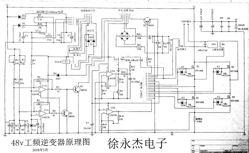
here is one, oreo
wronger than a phone book full of wrong phone numbers
wiseguy Guru Joined: 21/06/2018 Location: AustraliaPosts: 1296
Posted: 05:48am 01 Jun 2024
Copy link to clipboard
Print this post
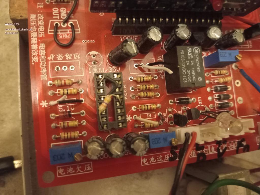
I cant relate the PCB written values with the ones on the schematic also the schematic uses 2 x LM358s (both dual opamps) the PCB appears to be set up for the LM324 quad opamp, the two trim pots are not 50K as per schematic but 20K. So there are subtle differences between them. Fundamentally the control voltage point is set by the 5V1 zener. If the two resistors across C1 & C2 (R3 & R4 on the schematic) are both 10K then at 5.1V they will have a current of 5.1/10000 or 510uA at the decision point.
The pot values on the PCB appear to be both 20K lets make R1 & R2 4K7. At 510uA and max pot setting the max value of R1 (+20K pot) is 24.7K added to the 10K bottom resistor of the chain and multiplied by 510uA = 17.7V now with pot at minimum = 14K7 x 510uA = 7.5V. So knowing that the 2 input voltage trip points can be varied between 7.5V & 17.7V you can set the overvoltage and undervoltage points easily.
First set R3 pot to maximum resistance and R4 to minimum. Set the input voltage to the minimum shutoff value ie 9V now adjust R4 (increase resistance) whilst monitoring the base voltage of Q1 (which should be at 0.6V to start with). When the base of Q1 becomes ~ 0V the low voltage stop point is set (there is hysteresis with R6) so the input voltage will need to increase by a volt or two to set the inverter on again.
Now to set the overvoltage shut down, set the input voltage to the desired shutdown voltage lets say 16V. Again monitor base of Q1 which should start with ~0.6V) Now adjust R3 (decrease resistance) until base of Q1 goes to 0V (or very close to that) and the overvoltage trip point is set.
The rest of whether it will work is up to you ! Edited 2024-06-01 15:54 by wiseguyIf at first you dont succeed, I suggest you avoid sky diving.... Cheers Mike
poida: Thank you for the schematic. It is helpful. wiseguy: Thank you for the insight. I hope I can short R1 and R2 to zero ohsm. Easiest to do with existing test jumpers. As per poida's schematic there seems no problem doing this. oreo: Thanks for taking time.
I had hoped overload and short circuit working ok for 12V by default, but it did not work with forced on from socket jumpers. May start new thread for that.