Notice. New forum software under development. It's going to miss a few functions and look a bit ugly for a while, but I'm working on it full time now as the old forum was too unstable. Couple days, all good. If you notice any issues, please contact me.
I obtained a bare PCB where there is a jumper to be connected on EGS002. It is output of the overload protection circuit build around LM324. Where is it to be connected on EGS002? How is it different from short circuit protection (Ifb)?
rustyrotors Newbie Joined: 07/01/2023 Location: United StatesPosts: 36
Posted: 07:58am 13 Jun 2024
Copy link to clipboard
Print this post
i believe it connects to positive side of C24. the egs002 has a design flaw where U4 causes the FETs to blow up in an over current situation. an easy fix is remove U4 short C19, and remove R26, which will leave IFB function intact. im not sure of the purpose of the jumper wire, but it could be an attempt to fix this flaw without modding the egs002, but i know it does not work, because mine still blew up before i did the mods
tinyt Guru Joined: 12/11/2017 Location: United StatesPosts: 559
Posted: 01:02pm 13 Jun 2024
Copy link to clipboard
Print this post
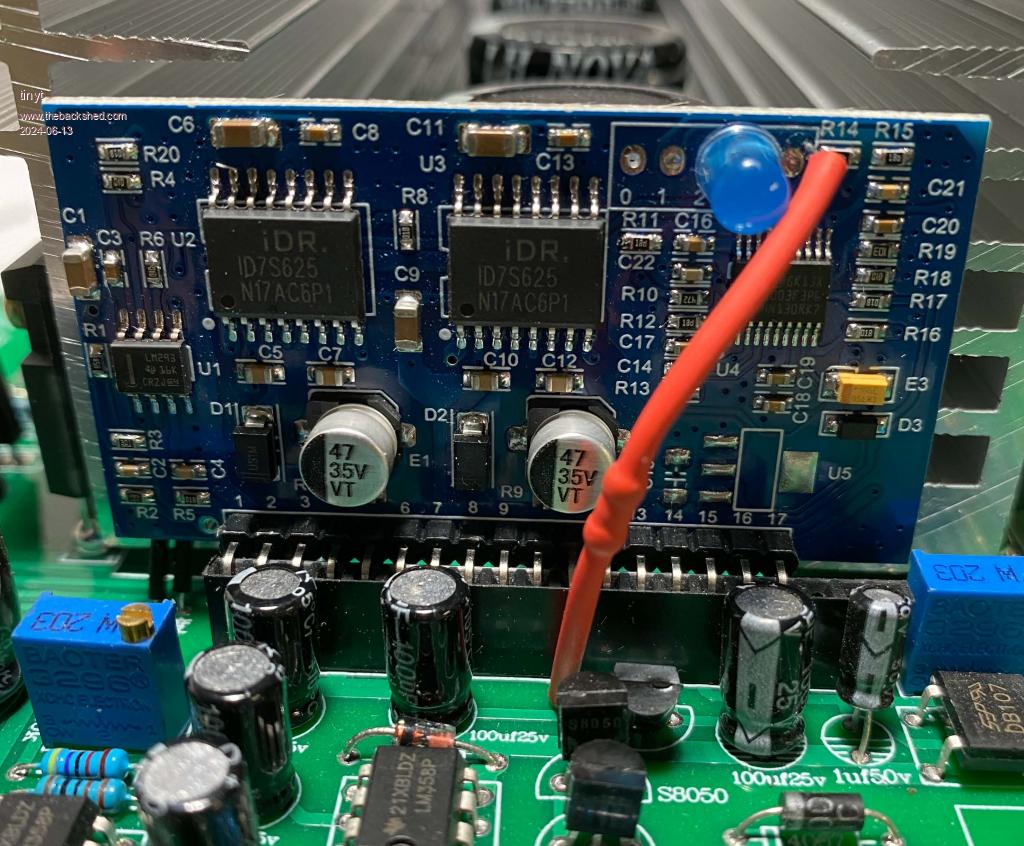
The chinese inverter I purchased also has a 10Kohms jumper to the controller board and it is using a 'century' controller instead of an egs002. I replaced it with a modified egs002 and did not connect this jumper.
For reference, here is partial circuit trace I did of the inverter.


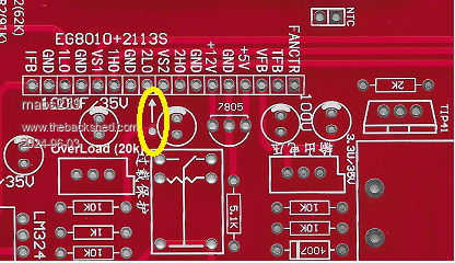
.jpg)
.jpg)
.jpg)