Notice. New forum software under development. It's going to miss a few functions and look a bit ugly for a while, but I'm working on it full time now as the old forum was too unstable. Couple days, all good. If you notice any issues, please contact me.
poida Guru Joined: 02/02/2017 Location: AustraliaPosts: 1476
Posted: 07:07am 18 May 2025
Copy link to clipboard
Print this post
I wanted to know the power draw from a standard kit eg. https://www.jbhifi.com.au/products/starlink-standard-kit-latest-generation
my battery in the camper is 2 x 12V 100AH Lithium, in parallel The inverter is a 275 VA, 12V Victron which draws about 0.5A @ 13V with no load.
The starlink terminal starts at about 5 W, powering the wifi then it needs about 100W booting up the antenna and once settled down and online it needs around 55W these power levels are taken from testing it using bench power supply set to 56.5V DC output. this 55W is equivalent to about 4.3 Amps at 13V
When powered by the inverter it uses 5-6 Amps at 13V This means the cost of the inverter and starlink power supply losses is about 2A I thought maybe use a DC boost converter but I doubt it would be worth it and even less efficient.
The cable connecting the antenna to the terminal/wifi is very special and expensive. You get a 15M cable with the kit. the 45M cable is $270 from Harvey Norman
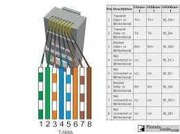
The connectors are RJ-45 and the outer cable shield is connected to the metal outer of the RJ-45 connectors. The cable is Cat6. I want a much longer cable than the 15M since we stop at places where there are plenty of trees. You need no trees obscuring about 1/2 of the sky for it to work well enough. I made a 50M cable, using Cat6 cable and normal cheap all plastic RJ-45 connectors. You need to wire them as shown to get the 1Gbit functionality.
Testing this home made cable had 240 Mbit speeds from the satellites and it was that when using the starlink's kit 15M cable. This cable cost me nothing since I had connectors, cable and tool already at work.wronger than a phone book full of wrong phone numbers
phil99 Guru Joined: 11/02/2018 Location: AustraliaPosts: 3293
Posted: 08:08am 18 May 2025
Copy link to clipboard
Print this post
Yes and no. Half a century ago went through a similar exercise. Wanted to take a portable colour TV on a comping holiday but it didn't like my homebrew 240V modified square wave inverter. Internally it ran off 115VDC at 0.45A.
Wasted a lot of time trying to get an inductor based boost converter to do it efficiently. The answer was a transformer boost converter producing up to 60V HF AC feeding a voltage doubler rectifier. Feedback then brought it back to 115V. The oscillator was just a NE555 with feedback going to pin 5. Output transistors were MJ802, gross overkill but gave a low VCEsat. MOSFETS were not readily available then. Efficiency was roughly 90%. Edited 2025-05-18 18:15 by phil99