
|
|
Forum Index : Electronics : Toroid Candidate
| Author | Message | ||||
Bryan1 Guru Joined: 22/02/2006 Location: AustraliaPosts: 2100 |
G'Day Guy's, Well I took up this toroid to Rogers this morning to get an opinion and due to the weight of this he did say it say it could be suitable. Basically he mentioned I will find when the wire is is off along with all the tape it will be tightly wound coil of very thin silicon steel. 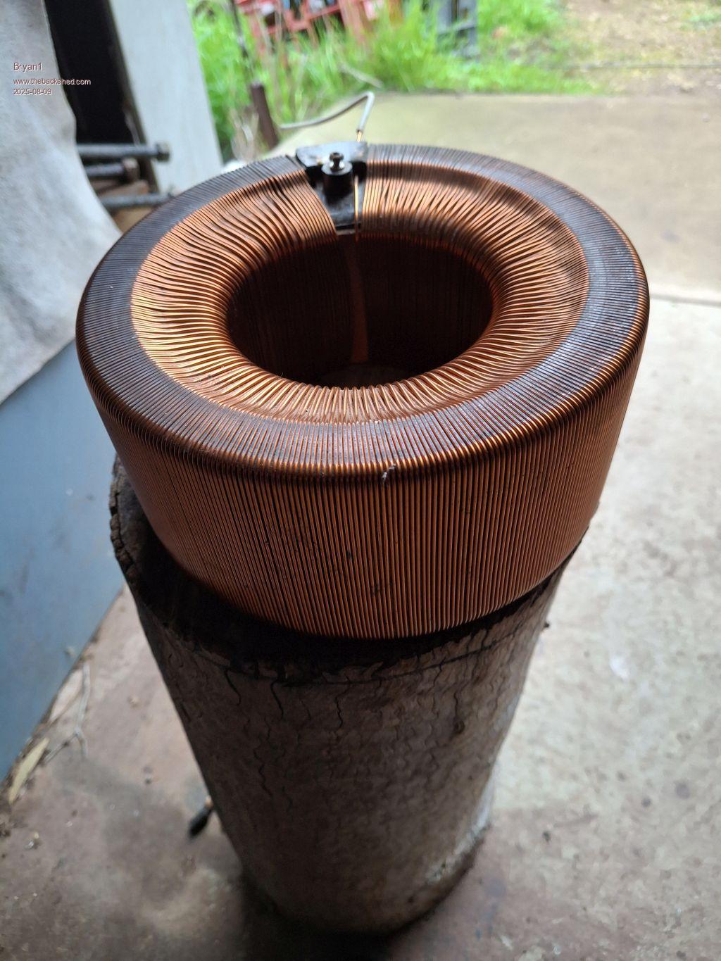 Now this toroid came out of my old Variac and when I say old I can remember seeing Dad using this before I was a teenager. So I reckon this one is from the 50's or early 60's where the poms made things right. Now as I have 2 spools of 1.6mm wire I'm thinking winding a 2 inhand secondary but how many turns is the unanswered question. Now one may ask why go 2 inhand of such thick wire well this toroid will going on my first Madboard which will be coupled with a 5Kw Goodwe gridtie and 6Kw of solar so the back feeding rate is going to be pretty high. Tomorrow I will strip it down so we can have a look at it and it may be finally time to get that roll of mylar out that I bought 20 years ago. Cheers Bryan |
||||
| Bryan1 Guru Joined: 22/02/2006 Location: AustraliaPosts: 2100 |
Ok bugger tomorrow was too long to wait  so here we are with a 172 diameter 90mm hole and 60mm high bare toroid so here we are with a 172 diameter 90mm hole and 60mm high bare toroid 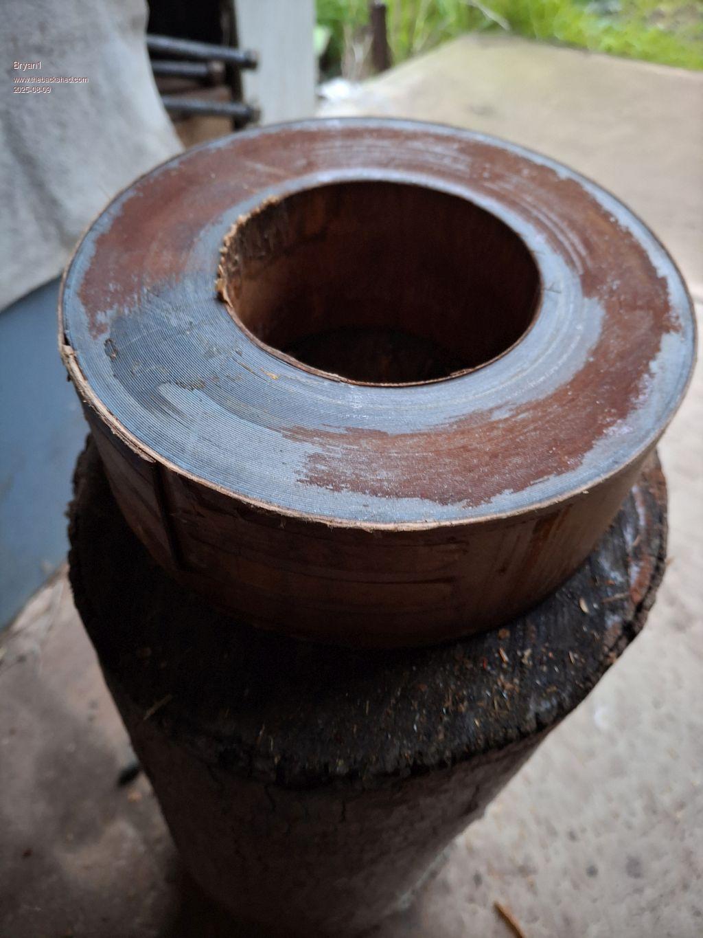 It didn't take long to strip the wire off and a quick tap with a hammer and chisel soon got the bakealite covers off to expose the toroid. Each edge will need to ground so a nice radius is there for the new wire. Cheers Bryan |
||||
| Godoh Guru Joined: 26/09/2020 Location: AustraliaPosts: 667 |
Looks good Bryan, what are the measurements of the core? Also what guage of wire is on it now? The last two torroids I made I wound with a high voltage side of 2.8mm sq, wire. The secondary was flat glass insulated bar of 12mm x 3mm. Then my inverters are 24 volt, If you are looking at getting 5kw out of the inverter or into the inverter then you need to have about 3.2mm diameter wire so your two 1.6mm wires should do the job. Have fun with it, Pete |
||||
| Godoh Guru Joined: 26/09/2020 Location: AustraliaPosts: 667 |
I see you already did the unwind. That core is a bit too small. It would only be around 1kva at that size. The last core I would was 172mm OD 100mm Id and 140mm high. That worked out to be around 4.5kva. Do you have another core or two to stack on top? |
||||
| phil99 Guru Joined: 11/02/2018 Location: AustraliaPosts: 3293 |
Deleted. No longer relevant as you have unwound it. Edited 2025-08-09 18:18 by phil99 |
||||
| Bryan1 Guru Joined: 22/02/2006 Location: AustraliaPosts: 2100 |
Hi Pete the old wire was 1.2mm now after I get that insulation tape off I reckon the OD will be around 170mm and the bore a tad over 90mm. Now when I did mention about going 2 inhand to Roger today he did mention about winding side by side or winding one over the top and connecting both together. As winding a single wire will be much easier but eh I will have the guru of winding helping me with this Some may ask why I am going with the madboard when I do have a couple of the new inverter boards from Mike. Well I do have all the parts for building this inverter and as we can have 6 fets and each leg I will be putting 24 HY5608 fets so the board can handle the big currents with ease. Eh mate why does retirement have so many jobs yesterday I tried heating up the carrier for my 6" jaw crusher only to find the oxy line was perished  so bought a new 10 mtre oxy/LPG hose today but the question of this toroid came over everything. so bought a new 10 mtre oxy/LPG hose today but the question of this toroid came over everything.Look I will come clean on why I need so much power I make my own moonshine and to date just used a BD burner and used LPG. Now to use elements for my 100 litre boiler there is a 3.6Kw heating element on all the time and a 2.4Kw on a voltage controller. Now to run elements off the grid does mean I do make a beefy inverter to handle the current draw from the elements. |
||||
| Bryan1 Guru Joined: 22/02/2006 Location: AustraliaPosts: 2100 |
This morning machined the ridge off the top former 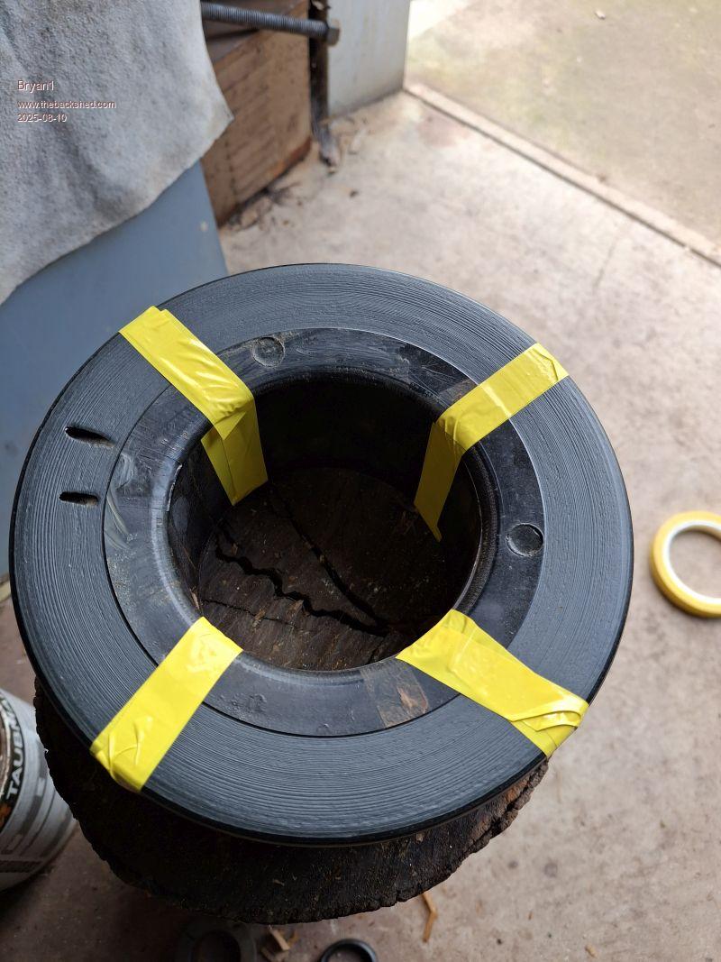 Then finally got my roll of Mylar out of the corner and wrapped up the toroid 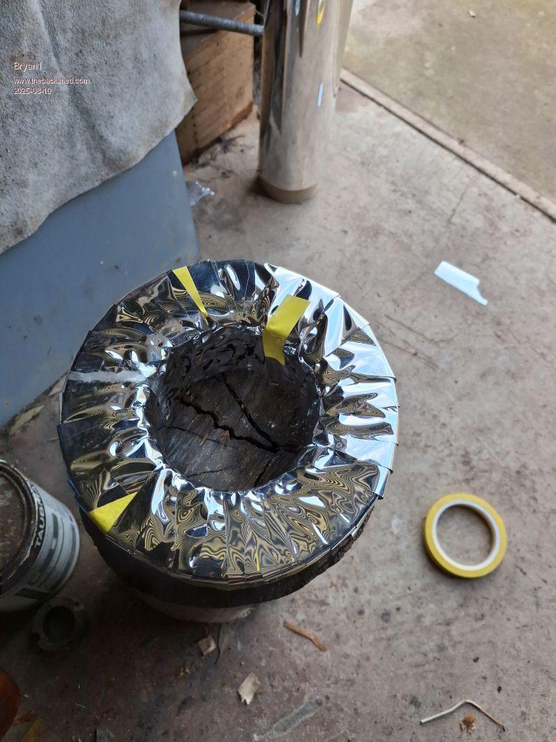 Now here is a pic of the Mylar roll 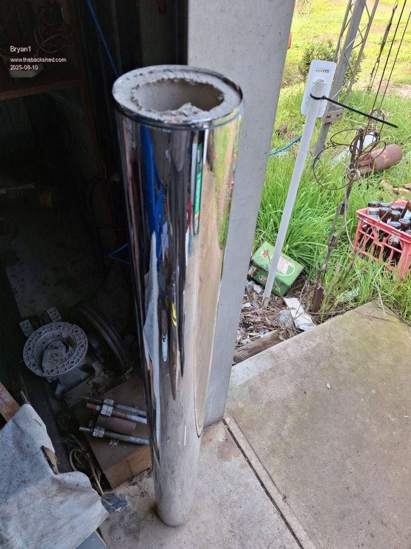 Roger did give me a link to a couple of Aerosharps in Melbourne and I asked a friend over there to get them for me so next weekend he will pick them up  My friend did say he was going to come over and see me so he going to bring them over for me. My friend did say he was going to come over and see me so he going to bring them over for me.So my idea is to use this toroid on that inverter I have made which will free up a aerosharp toroid then for my Madboard it can have a 3 stacked toroid just so I can get the best out of the inverter.Cheers Bryan |
||||
| Bryan1 Guru Joined: 22/02/2006 Location: AustraliaPosts: 2100 |
So I asked Co Pilot the question of 13 turns on the primary at 24 volts for a 240 volt output and we finally settled on 130 turns. Now I said I was going 2 inhand and the reply was yes that will double the current rating. Now I did ask about winding one 130 turn layer then one ontop after insulating and the answer was NO don't do it unless the length of the 2 wires are exact. I would of thought the turn would of been closer to 200 but eh I'm still learning and this will be my first toroid rewind. |
||||
| Bryan1 Guru Joined: 22/02/2006 Location: AustraliaPosts: 2100 |
Hi Pete I did measure the toroid in my Kipoint inverter and it is roughly the same height and diameter and the inverter is rated for 3Kw. Now if I may ask as I am on the same 24 volt setup how many turns on the secondary did you do and I assume you did 13 turns on the primary. Cheers Bryan |
||||
| Godoh Guru Joined: 26/09/2020 Location: AustraliaPosts: 667 |
Hi Bryan here are some figures I calculated when i did my last transformer Torroidal transformer calculations, Area of core, (width of core x height ) /2 eg big tranny, 90mm wide, by 100mm high 9 x 10 = 90 /2 = 45 cm squared. Turns per volt calculated by the 42 rule So 42 / core area 42 / 45 = 0.93333 turns per volt so 230 volt winding has 230 / 0.9333 = 214 turns 13 volt winding has 13/ 0.9333 = 12 turns wire guage allow 4 amps per mm diameter. So primary will have 20 amp capacity and be wound with 5mm squared wire ( 1 x 2.5mm) Secondary will have 200 amp capacity so will need 50mm squared wire. |
||||
| Godoh Guru Joined: 26/09/2020 Location: AustraliaPosts: 667 |
Hi again Bryan, 13 turns should be fine on the 24 volt side. It gives a bit more headroom when the transformer is loaded up. The inverter should have no trouble regulating the output, I usually add a couple of turns to the 230 volt side too, just so the sinewave doesn't get too clipped. Pete |
||||
| Bryan1 Guru Joined: 22/02/2006 Location: AustraliaPosts: 2100 |
G'Day Pete, Ok going with my core 172 diameter by 60 high with a 90mm hole So 172-90/2 = 41 x 2 wide by 60 high 8.2x6/2 24.6 cm squared 42/24.6= 1.7073 volts per turn So 230/1.7073= 134.7 turns So Co Pilot was pretty spot on with using 130 turns and going with that extra 4 turns will give the headroom. If all of this is right I do hope Roger sees this as I am keen to learn how to wind a toroid |
||||
Revlac Guru Joined: 31/12/2016 Location: AustraliaPosts: 1277 |
Numbers don't look right quite right Bryan. This calculator used to be my goto https://www.electricaltechnology.org/2014/02/maximum-flux-density-bmax-calculator.html Cheers Aaron Off The Grid |
||||
| Godoh Guru Joined: 26/09/2020 Location: AustraliaPosts: 667 |
HI Bryan you see to have mixed the formula up. 42 divided by the core area gives Turns Per Volt. Your transformer would have 1.7 turns per volt So to get 230 volts out you would need 391 Turns Somehow I have written a divided sign when it should be a multiplication sign SORRY So it should be The 230 volt winding has 230 X 1.7 which is 391 turns the 13 volt winding should be 13 X 1.7 which is 22.1 turns OOOPPPSSS Pete |
||||
| Bryan1 Guru Joined: 22/02/2006 Location: AustraliaPosts: 2100 |
Thanks for that Pete well it does look like single strand will be the go and this toroid can go on that inverter I made using the ali express board. This will free up a aerosharp toroid.In the morning I will wind a single turn to get the wire length then work out which 1.6mm spool to use to ensure there is enough wire. I did mention to my mate who does go 4x4 camping if he upgraded his battery bank he could have that inverter and he did say he would gladly pay for what it cost me. As he is going to pickup those 2 aerosharp inverters for me I did suggest meeting him 1/2 way where another mate who lives at Horsham so we can all have lunch together. So I will need to get a move on getting this wound and tested as this trip will be happening in a few weeks. |
||||
| Godoh Guru Joined: 26/09/2020 Location: AustraliaPosts: 667 |
Hi Bryan my spreadsheet says you will need about 95 metres of wire for the primary if you just use one wire in hand Around 1.2 kg of 1.6mm wire would be about that much good luck with it. Making a hoop big enough helps. The last transformers I did I made a hoop from a length of 32mm conduit. Then cut a slot around it to let me load the wire. I hung the hoop off a rope tied around my rafters in the shed so it was easier to control. That gave me 4 metres of wire per turn which worked out great as I was using 2.8mm magnet wire Pete |
||||
| Bryan1 Guru Joined: 22/02/2006 Location: AustraliaPosts: 2100 |
The last I weighed those 2 spools both were over 3Kg's each and as I haven't wound a toroid Roger has agreed to help me and teach me as we go. My mate just got back to me saying he just bought an inverter and he should of asked me first. |
||||
| Bryan1 Guru Joined: 22/02/2006 Location: AustraliaPosts: 2100 |
Hi Pete Cobbler worked out the rule 45 was a better match for my toroid which worked out to 432 turns for the secondary and 26 turns for the primary. Now I worked out with a 90mm bore using 1.6mm wire I can get 176 turns with no gaps so I worked out 144 turns a layer for 3 layers works out nice. Now I just did a single strand which measured 230mm so with 432 turns 99.36 metres will be needed but I reckon 110 metres would the be the best to allow for hand winding. Now lets say we need 35sq mm for the primary how much 1.6mm wire would be needed inhand as about 6.5 metres will be needed and twisting the 1.6mm wire should be OK. Anyway it's all arranged for my mate in Melb to pick up those 2 aerosharps so I should have them within the next month so I can finally get on and finish that first Madboard. Regards Bryan |
||||
| Godoh Guru Joined: 26/09/2020 Location: AustraliaPosts: 667 |
HI Bryan, To use different guages of winding wire one first calculates ( or looks up a chart) to find out how many circular mills the wire is. 1.6mm wire is 3970 circular mills. 35mm wire is 69000 circular mills So you would need 17 or 18 1.6mm wires in parallel to be the equivalent of a 35mm conductor. Now the challenge will be getting them to first bend around the high voltage winding and core, and second to fit into the hole that is left after winding the high voltage winding on. Welding cable would be much easier to work with , but if you are going to use what you have then after you have wound the high voltage winding on, get something about the same size as the 17 or 18 wires you are going to use for the low voltage side and make sure you have enough room to fit them in. cheers pete |
||||
| The Back Shed's forum code is written, and hosted, in Australia. | © JAQ Software 2026 |
