
|
|
Forum Index : Electronics : Recovering from disaster by using Wiseguy's mosfet driver design
| Page 1 of 3 |
|||||
| Author | Message | ||||
| tinyt Guru Joined: 12/11/2017 Location: United StatesPosts: 559 |
I made 3 of these using modified chinese inverter power boards. 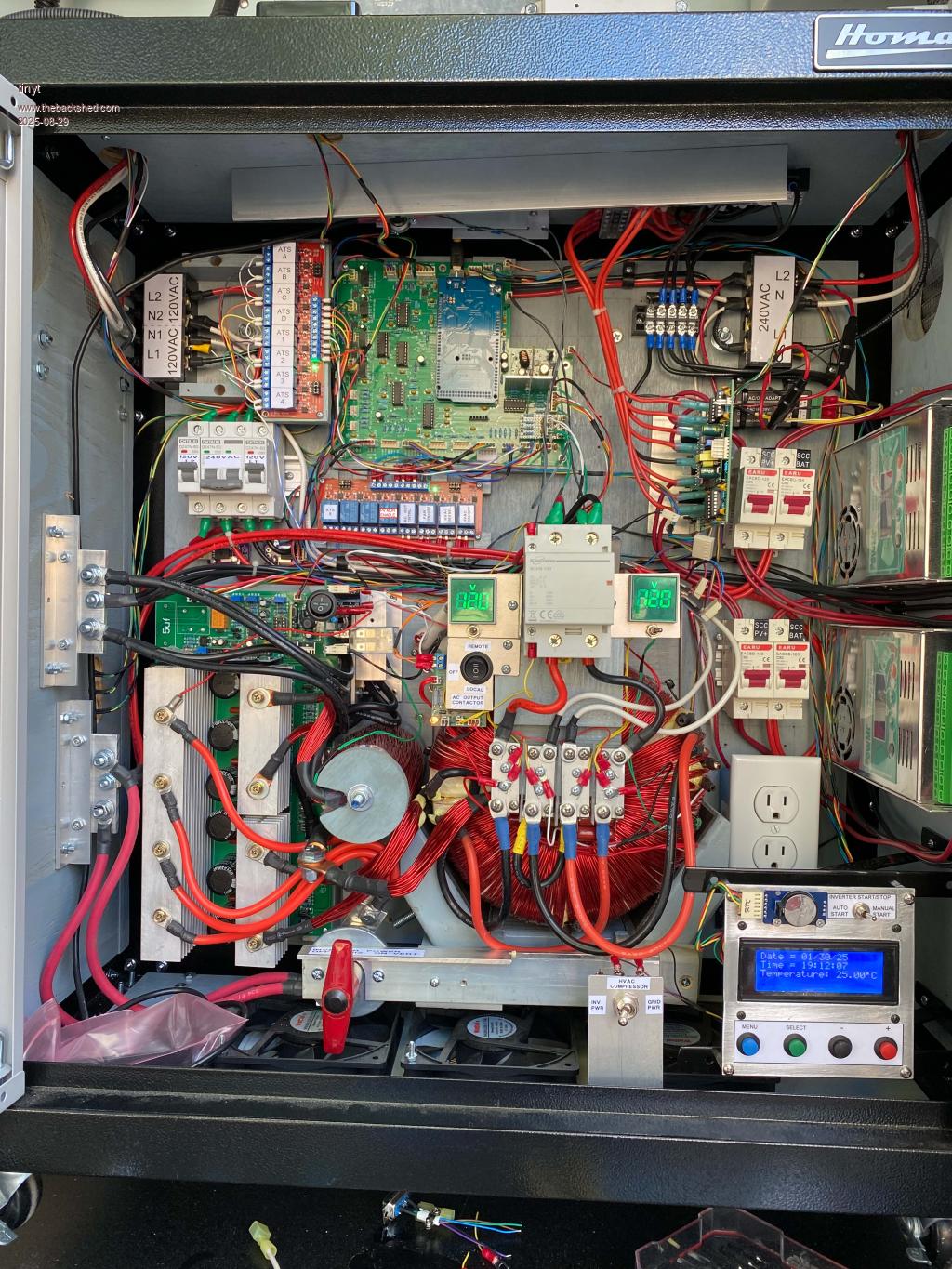 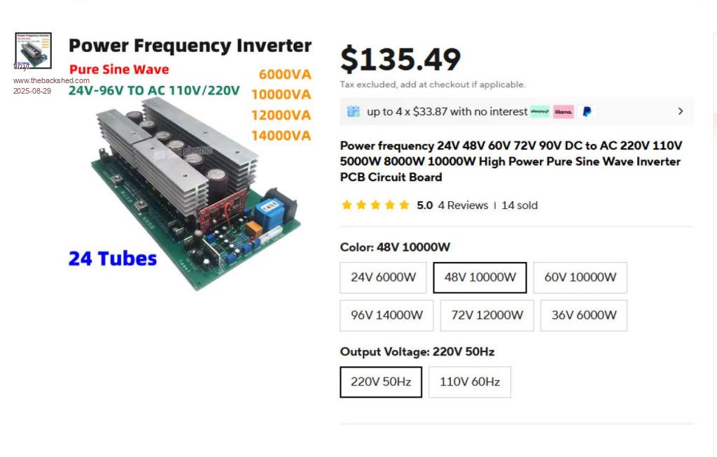 Two are currently working at each of my two son's house, powering half of their household loads. During install, we tested succesfully start-up of their HVAC compressors. But it was not part of the household load. Last week, one of my sons connected the HVAC compressor to the inverter and BOOM! - I have now joined the elite club of mosfet destroyers. Edit: Picture was taken after loosening the mosfet mounting screws. 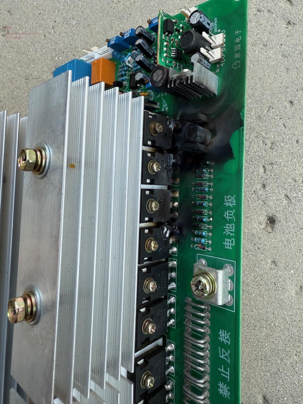 In addition to adding a soft-start modification to the compressor wiring, I am now attempting to adapt Wiseguy's robust mosfet driver design to the chinese inverter power board. Opto Inverter.pdf I hope I will not make mistakes. Now waiting for ordered parts while I figure out how to install and connect them. Edited 2025-08-29 01:02 by tinyt |
||||
| analog8484 Senior Member Joined: 11/11/2021 Location: United StatesPosts: 203 |
Sorry to see the blow up but interested to see how you modify the board. Not sure if you can do it but it would be great if you could get some scope captures of the drive wave forms before and after the mods to see if Miller shoot through is at play. One thing that has stuck in the back of my mind is the Miller current induced false turn-on's found in these egs002 power boards that I saw in a poida post a while back. I agree with him that it's likely a main culprit that degrades FET's over time and behind many of the "sudden" blow up's. I don't have proof but I suspect negative drive bias voltage on the upper and lower FET's would be more helpful than opto interlocking. |
||||
| tinyt Guru Joined: 12/11/2017 Location: United StatesPosts: 559 |
I was also wondering why the upper mosfets don't have negative bias. Maybe, it will also help to add it. Edit: Here is schematic for 3 bias'ed drivers. Caution - not sanity checked. Opto Inverter 3-Bias.pdf Edited 2025-08-29 06:13 by tinyt |
||||
| Godoh Guru Joined: 26/09/2020 Location: AustraliaPosts: 667 |
Just wondering TinyT, did you modify the 8010 boards on your inverters to prevent some of the problems that were built into them. Years ago Oztules showed how to modify the boards, because they had a habit of over protecting and causing blowups like your board has had. I have a few of those inverter boards running at my place. So far the only inverters that have died on me from Mosfet explosions were PowerJack inverters. After a few blowups on them I rewound the transformers and used the aliexpress boards you have used and have not had a blowup since. My 4kw shed inverter has been running now for about 3 years from memory and works great. The PowerJacks did not like voltage dips caused by starting inductive loads. good luck pete |
||||
| tinyt Guru Joined: 12/11/2017 Location: United StatesPosts: 559 |
That inverter board came with an undocumented spwm board. .jpg) Claimed by the seller to be compatible with EGS002 (8010 chip). So I replaced it with EGS002(modified per oztules plus some more modifications). 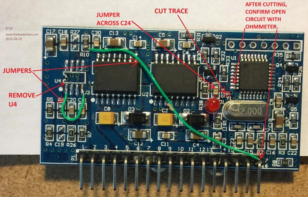 I have 3 of those inverter boards which I have reversed. 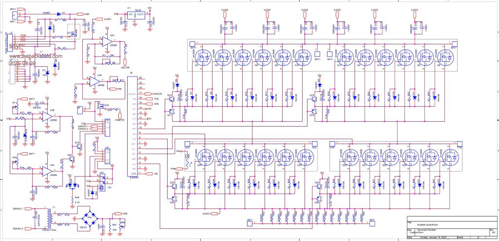 Then I modified to suite my requirements. 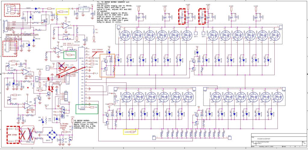 Two of them have been running for about 6 months until one blew up. Prior to installing at each of my two son's house, they were tested with air compressor, incandescent flood lights, and momentarily with the same HVAC that it blew up with. The start up load when it failed was a 5-ton HVAC with a compressor rated at 230vac, LRA of 148A (RLA is 24A). We waited 10 minutes of no compressor power before connecting it to the inverter. The toroid is a re-wound 5KVA but together with the inverter power board was tested to be able to deliver up to 8KVA for a few minutes with forced air cooling. With a load LRA of 148A it probably experienced a load of 148 x 230 = 34 kVA. I think it is too much even for this toroidal inverter. That is why I think I also must add a soft-start module to the compressor. Edited 2025-08-29 14:11 by tinyt |
||||
| Godoh Guru Joined: 26/09/2020 Location: AustraliaPosts: 667 |
It sounds like you have it under control. That starting load you are talking about is huge, I put the blowups on the Powerjack inverters down to starting loads. They failed when using power tools, especially they did not like my 1500 watt power saw. I don't know if it would help your situation but to help with dips due to starting inductive loads I added a 500 farad capacitor bank in parallel with my batteries. The capacitor bank is capable of supplying 1900 amps, (they are used for starting diesel trains.) It may be that my inverters are better than the powerjacks or it may be the capacitor banks assistance but I haven't blown an inverter up since fitting them. I am crossing my fingers. I don't have any loads like air conditioners though. I use normal shed power tools on my inverter. air compressor, power tools, wood splitter, MIG welder. So far so good. I hope the new system you are using works fine. Good luck Pete |
||||
| phil99 Guru Joined: 11/02/2018 Location: AustraliaPosts: 3293 |
A conventional single phase induction motor / compressor combination really requires a variable frequency drive for a soft start. A conventional soft start circuit may prevent the motor developing enough torque to turn over the compressor, making the situation worse. The other option is a very beefy solid-state relay or triac to switch it on at the peak of the AC cycle. With the first half cycle reduced to a quarter cycle the chance of pushing the stator into saturation is greatly reduced. Saturation briefly takes the current well above the LRA. The normal inrush current will follow but your inverter should be able to cope with that. |
||||
| tinyt Guru Joined: 12/11/2017 Location: United StatesPosts: 559 |
Hi Pete, thanks. Will be posting here of the progress and whatever the result. |
||||
| tinyt Guru Joined: 12/11/2017 Location: United StatesPosts: 559 |
Hi phil, thanks for the info. VFD might be too expensive. Even the Micro Air Easystart is not affordable, besides it requires wiring modifications to the compressor circuit. I am leaning towards your suggestion of the triac option with a dry contact relay to bypass the triac after a preset delay. But first I have to fix/improve the inverter power board which I have switched with mine to get my son's inverter working. Edited 2025-08-29 23:09 by tinyt |
||||
| tinyt Guru Joined: 12/11/2017 Location: United StatesPosts: 559 |
Hi analog, Looking again at the EGS002 datasheet, I think you are right that the opto interlocking feature is not needed. It already has a dead time selection jumpers with a default setting of 300 nS (close to Wiseguy's driver's calculated RC time constant value of 360 nS). So, I think what I only need is the addition of drive bias voltage. and avoid excessive overload. Am I right? Edit: But then I think I still need the opto isolation without the RC delay to make the negative bias voltage work. Edited 2025-08-30 10:25 by tinyt |
||||
| phil99 Guru Joined: 11/02/2018 Location: AustraliaPosts: 3293 |
Looked up the Micro Air Easystart and it clearly is an improvement on a conventional soft start circuit, hence the high price. It appears to only control the motor main winding current, as that is the main problem, while the start/run capacitor and winding get full volts. This ensures good starting torque. The start/run capacitor prevents the start winding drawing excessive current anyway. Applying the same method to the triac quarter cycle starter would be a good idea. Build it into the air-con. |
||||
| tinyt Guru Joined: 12/11/2017 Location: United StatesPosts: 559 |
Hi phil, Thanks, have to figure out how to do this. Also, revisiting this other forum thread. Edited 2025-08-30 11:26 by tinyt |
||||
| phil99 Guru Joined: 11/02/2018 Location: AustraliaPosts: 3293 |
Something like this. The existing controller relay contact could be in either L1 or L2. 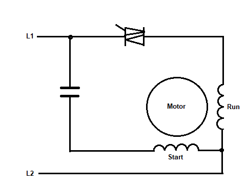 |
||||
| tinyt Guru Joined: 12/11/2017 Location: United StatesPosts: 559 |
Thanks. |
||||
| analog8484 Senior Member Joined: 11/11/2021 Location: United StatesPosts: 203 |
Yes, the deadtime setting is already there. Also, EGS002 has cross-conduction prevention/interlocking output transistors. I believe the opto interlocking came about due to custom EG8010 boards without cross-conduction prevention rather than the EGS002. Still, having interlocking in the opto's won't hurt. Yes, I believe so. For sure, optos (with isolated DC-DC modules) are probably the easiest way add negative bias voltage. |
||||
| analog8484 Senior Member Joined: 11/11/2021 Location: United StatesPosts: 203 |
I am amazed the inverter was able to start a 5-ton A/C without a soft-start even once. Was there a difference in battery bank size between the successful test and the blow up? That's almost 700A DC current? Now, I am even more amazed the inverter was able to start the A/C even once  |
||||
| tinyt Guru Joined: 12/11/2017 Location: United StatesPosts: 559 |
No change/difference. When I was assembling them I added two 10000 uF to the existing six 3300uF bulk capacitors. I also beefed-up with more solder and solid wires the high current carrying copper traces at the back of the power board. Maybe they helped. 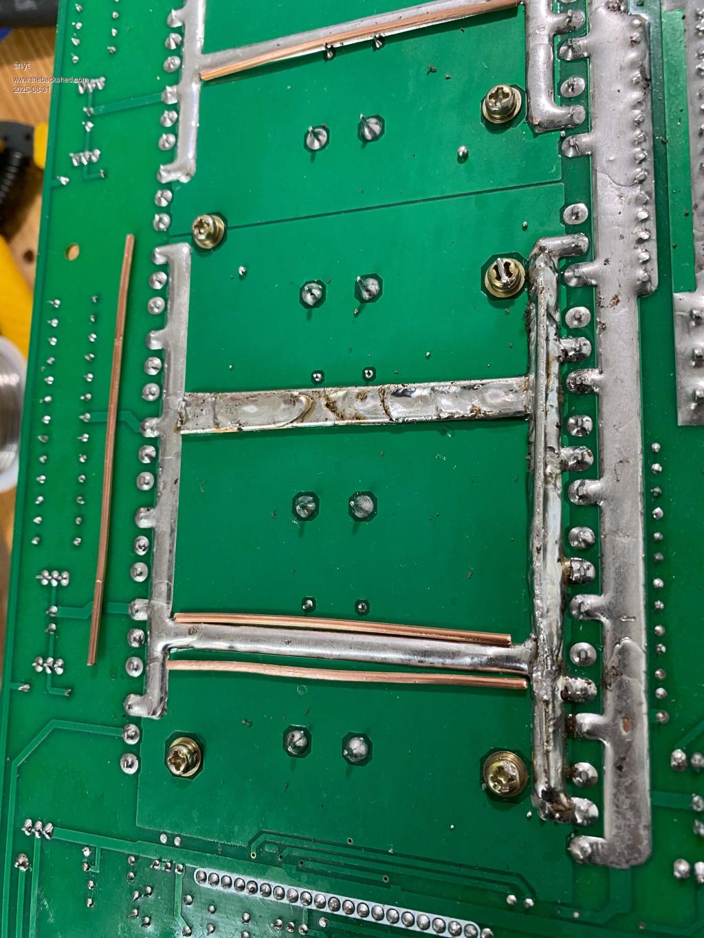 The battery bank is 16S3P EVE LF105. 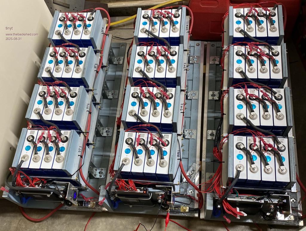 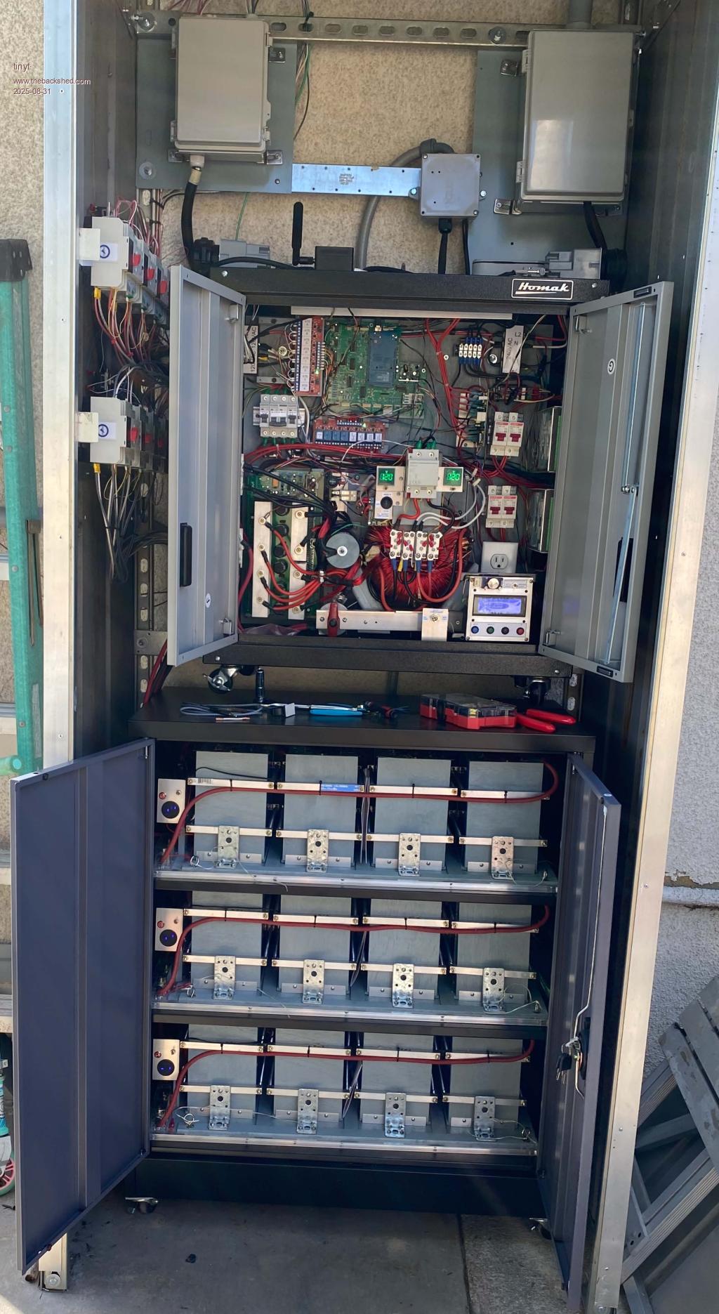 I was surprised also. The other same design inverter at my other sons's house ran his A/C on the inverter several times for a few minutes during testing. But it is an old smaller one with an LRA of 61A. I told him don't connect the A/C to the inverter until we connect a soft start. Edited 2025-08-31 09:41 by tinyt |
||||
Revlac Guru Joined: 31/12/2016 Location: AustraliaPosts: 1277 |
Interesting, I'm not sure if those inverter boards have low output voltage cutoff, and with what looks to a single toroid I suspect there was some AC voltage drop when starting the HVAC, if so the HVAC would receive much less current than the LRA rating and more like a sort start at that point, so yes it could start it and if lights where connected would have seen them dip/dim when starting large loads. Only going by the information provided, probably a scope and some voltage logging would show exactly what is happening. Nice looking build, would be interested to see how you go with a soft start.  Battery setup is looking good too.  Cheers Aaron Off The Grid |
||||
| tinyt Guru Joined: 12/11/2017 Location: United StatesPosts: 559 |
The AWG8 wire length from the inverter cabinet port to the compresser is about 82 feet both ways which is about .052 ohms resistance. Including the added grid/inverter transfer relay contacts and inverter output contactor contacts, maybe series resistance is .07 ohms. So roughly voltage drop is 148 x .07 = 10 volts at the compressor. Including load regulation limitation of the inverter, maybe there is a limited soft start. One of the four alarms of the EGS002 is undervoltage of the AC output and it is monitored in this inverter board. But detection and shutdown by the chip is 3 seconds after the event. One of the strange behavior of the EGS002/EG8010 that we found out is under certain monitored AC output voltage condition, it will trigger overcurrent alarm despite it being disabled. It took us over a month to figure a solution and we are still not sure if we really fixed it. But that is another story. |
||||
| tinyt Guru Joined: 12/11/2017 Location: United StatesPosts: 559 |
The plan is to proto-type four identical small boards and connected them as shown. Opto Driver_Bias.pdf |
||||
| Page 1 of 3 |
|||||
| The Back Shed's forum code is written, and hosted, in Australia. | © JAQ Software 2026 |
