
|
|
Forum Index : Electronics : Trying to repair a MIG welder
| Author | Message | ||||
| Jacob89 Newbie Joined: 10/09/2017 Location: AustraliaPosts: 40 |
Hi all. I've been trying to repair my father's Lincoln MIG welder. Its an older (but not that old) 250amp single phase transformer based machine. Its probably the last of the transformer based machines and also the last of the Australian built machines. I think Dad bought it new around 2008 or 2009. It has a small control PCB that has a DC power supply onboard for control voltage, a relay that I believe pulls in the large AC contactor and energises the transformer when you pull the trigger on the hand piece, and a DC motor controller that runs the wire feed motor. The problem is with the motor controller. Originally the potentiometer failed which the left the wire feed running at a fixed speed which made welding very difficult. I replaced the potentiometer with the closest replacement I could find. This worked fine for a while and then the wire feeder stopped working at all. I pulled the PCB back out and found one of the two mosfets that make up the speed controller had blown apart. I have no idea if this was caused by some underlying issue that also caused the original potentiometer to fail or if it's unrelated. I tried to source a replacement PCB from Lincoln but its no longer available. So that leaves me with two options, either I repair the PCB I have or add a separate DC motor controller for the wire speed. The mosfets are an 80n10 (at least the intact one is) which are no longer available, although there are equivalents available that should work. But I'm no electronics guru, so beyond soldering new components onto the board I don't really know what to do if theres deeper issues. I've considered just wiring in a cheap dc motor controller, but the motor supply is sourced from the same rectifier that provides the welding current, so the voltage is going to vary depending on the voltage setting of the welder, which from memory is from 30-70vdc. Maybe that's not really an issue though. If any of you electronics gurus have any bright ideas I'd really appreciate it. It would be really nice to get this machine running, it was a really nice welder when it was running, and it would be a real shame to scrap it just because of this annoying little fault. 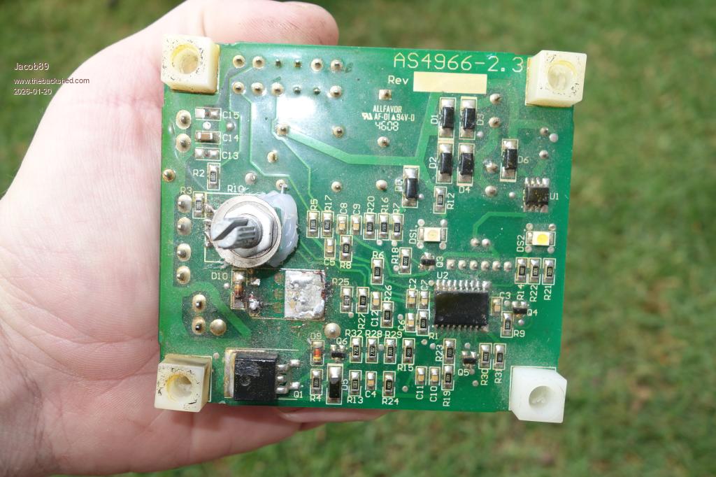 Please excuse the messy soldering and hot glue on the replacement potentiometer. And you can see where I removed the destroyed mosfet already. 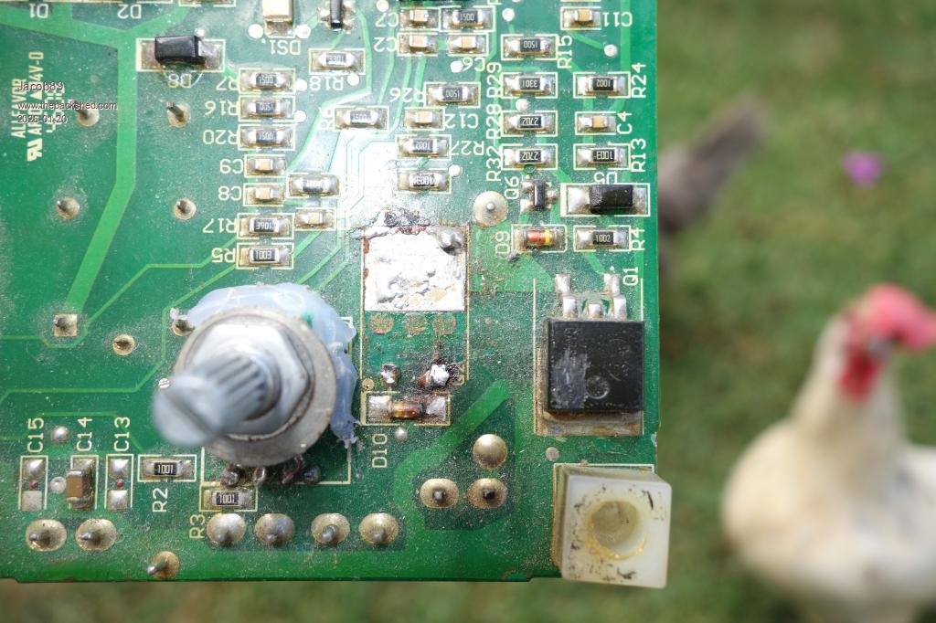 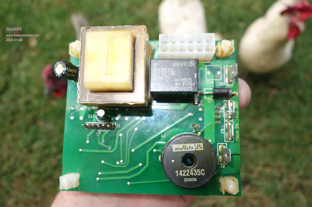 |
||||
| phil99 Guru Joined: 11/02/2018 Location: AustraliaPosts: 3293 |
To know if the blown MOSFET is the same as the remaining one or complimentary (P-channel or N-channel) you may need to trace and draw up that part of the circuit then post it here. Alternatively if you can identify the IC that drives them (U2) find a datasheet for it. They often have a typical circuit diagram for the intended application. The remaining MOSFET and associated components will need testing before repairs begin. I am guessing U1 could be a voltage regulator for U2 Vcc supply. Though it could also be an op-amp to generate the control voltage. Vcc will need checking too. The U2 datasheet will show what Vcc should be. If Vcc is ok we can use the datasheet to look for a way to test U2 and the remaining MOSFET without a load. The "Shotgun" approach is to just replace everything that you can't adequately test with a multimeter. |
||||
| Godoh Guru Joined: 26/09/2020 Location: AustraliaPosts: 667 |
Hi Jacob, from the voltage on the relay on the board it looks like the motor you are controlling may only be a 12 volt motor. If that is the case then you should be able to get a very cheap 12 volt motor controller from Ebay or Jaycar and use it to control the motor speed. All you need to do is pick a up where the feed for that board comes from, use a small transformer to drop the 240 volts down to 12 volts, rectify it and use a cheap motor speed controller board to do what you want.uNWmJ%2B%2BUShgI9tQz%2Fr620tDGFmDero66vxkmUDEXq3MavBIYiC%2F8ZJutluCRGjxpv%2F2JrWhAJr%2BP4ndhCy4STdKgzzEDG4VRYymxOVa1x86OpOdsQ5%2BQU76kA7ktxmMswjFQ5kGXDvSStU%2BIKhoqMrGCGTHR%2BuSoxrgNppBbQCKkYfp2Jna1uE%2BgP%2BcB67p4%2BKDvvZYUiC7iViNL470UIHdFzjamRKCbDjJZgXRQNRzdHfOhri0GW9wU0JXRA%2F4nOQ7n3dvY97xZ1rzt8hgT636zySjVH6EUmnO%2BNrbJOv%2BeFwn00sJabEUr3Qq2g%3D%3D%7Ctkp%3ABFBMssH-oPtm]https://www.ebay.com.au/itm/286530677413? Something like this controller on ebay should do the job Pete |
||||
| phil99 Guru Joined: 11/02/2018 Location: AustraliaPosts: 3293 |
The transformer on the PCB looks too small to power the motor. It is probably fed from the main welding transformer. Could be from the main secondary or an extra secondary. Trace the circuit of the rest of the welder and post it here. Also measure the motor supply voltage. Then it will be possible to see what needs to be done. |
||||
| The Back Shed's forum code is written, and hosted, in Australia. | © JAQ Software 2026 |
