
|
|
Forum Index : Electronics : Induction Tester
| Author | Message | ||||
Bryan1 Guru Joined: 22/02/2006 Location: AustraliaPosts: 2122 |
G'Day Guy's, Well this thread is for my trials testing out Poida's Induction Tester where I designed a PCB and got it working off the first draft  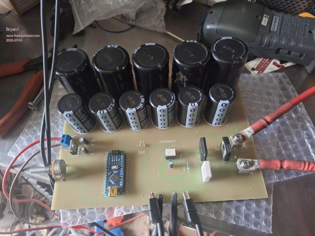 Now the board has 62,800uf worth of capacitors using 6 off 25 volt 10,000uf and 5 off of the 560uf capacitors off the aerosharp board. Now as I am still learning PCB design with Sprint Layout larger holes were needed as I only did 1.5mm holes. A 1.7mm drill was used to open up the holes so the larger components would go in. The 5K pot I used was a smaller size so to get it too fit I just soldered on some legs off a TO-247 old chip to each pot contact. Now the dual diode is also a TO-247 and I only put a 220 chip spacing so just bending the outer legs got it fitting nicely. I made a couple of inductors using a single 42mm diameter grey toroid with a 24mm hole and 17mm thick. I put 3 inhand 1.6mm wire with 5 turns, now my in DMM induction tester show .320mf the induction tester does show the true uf value with is very low. 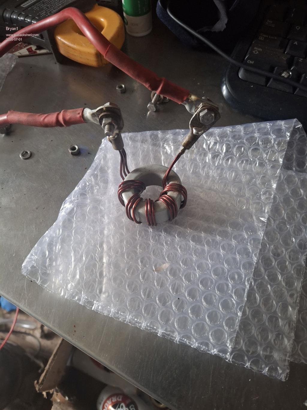 Now I have been using the 100us timebase so with Phill's suggestion I shortened the timebase to 50us and went with shorter pulses. 50us 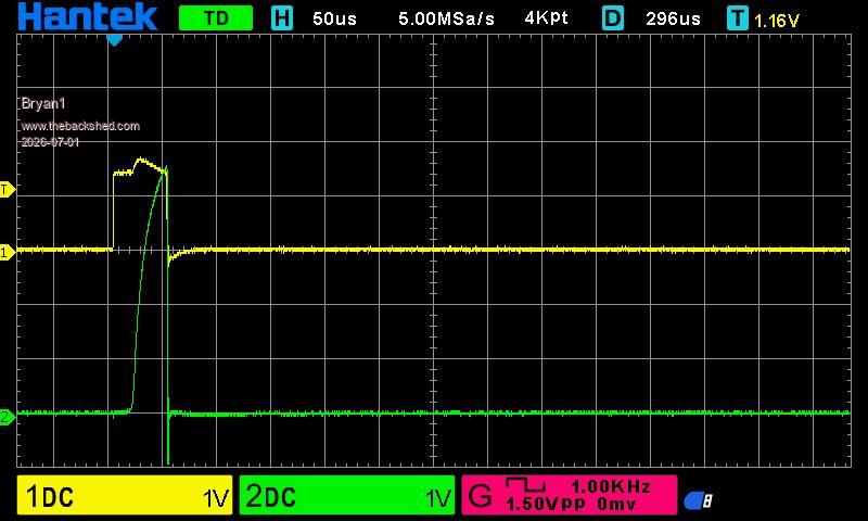 100us 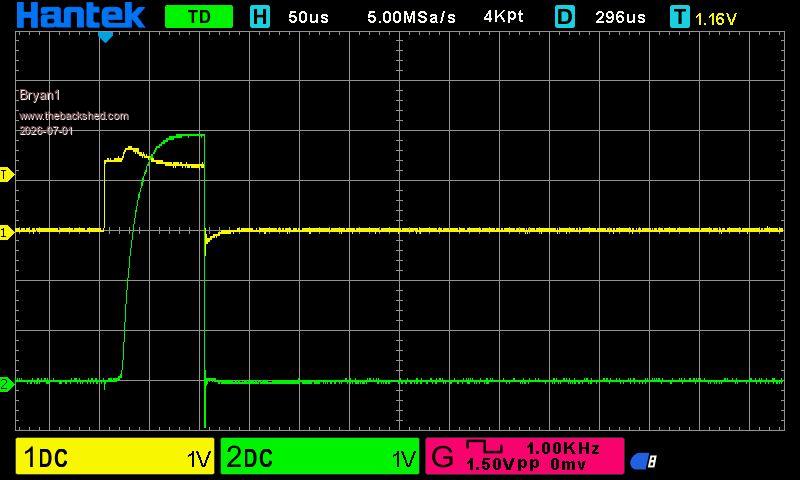 150us 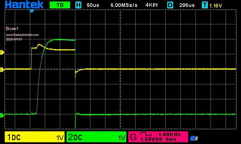 250us 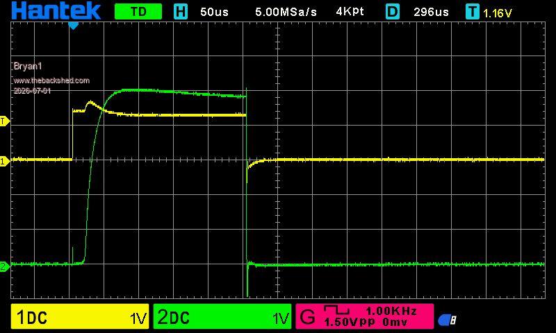 Now after 350us the sense pulse breaks down. So overall I am happy this induction tester is working and I do have 4 spare boards if members want any. Regards Bryan |
||||
| KeepIS Guru Joined: 13/10/2014 Location: AustraliaPosts: 2182 |
If that small toroid is high frequency material, the inductance would be tiny and it would likely saturate with just a few Amperes, it just looks like a complete saturation curve, or something is not quite right in the high current paths between the caps FET and choke? Of course, I could be totally wrong  NANO:Inverter V 8.2ks - Linux AvrDude GUI script V4.1 |
||||
| nickskethisniks Guru Joined: 17/10/2017 Location: BelgiumPosts: 481 |
It would be nice to see the cap voltage instead of the yellow, gate pulse? Like someone else allready said the cap voltage is probably sagging or close to zero, normally the current (green) should skyrock thrue the roof instead of being constant or bending to the right. Allthough the tester is doing what it's supose to do it lacks capacitance to sustain high current with limited voltage sag, you need to zoom in a lot to make sense of the curve, like 1-5us? Soon as your cap voltage sags to much the inductance you want to calculate based on di/dt is not true anymore, you need a constant (or close) voltage in the caps to have an accurate measurement. Best way to maximize the potential of the caps is to use as high voltage as they can handle and use smaller pulsewidth. 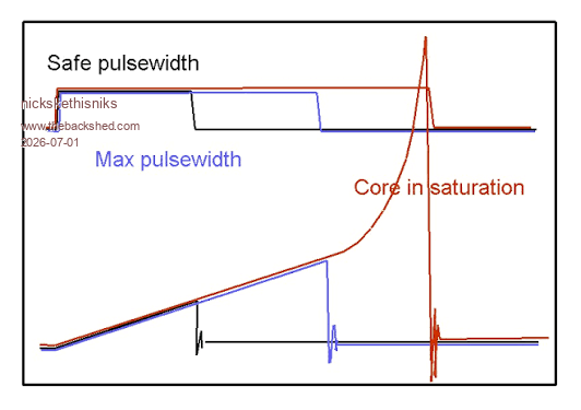 Edited 2026-07-01 17:21 by nickskethisniks |
||||
| poida Guru Joined: 02/02/2017 Location: AustraliaPosts: 1478 |
Nicks, that is an excellent illustration. wronger than a phone book full of wrong phone numbers |
||||
| KeepIS Guru Joined: 13/10/2014 Location: AustraliaPosts: 2182 |
This, but you will need to modify the circuit slightly for the opto supply rail. NANO:Inverter V 8.2ks - Linux AvrDude GUI script V4.1 |
||||
| Bryan1 Guru Joined: 22/02/2006 Location: AustraliaPosts: 2122 |
Well I am still learning all of this so please go easy on me, now today I will put that large aero-sharp choke back on and try with a shorter gate pulse. Now when I am testing my programmable power supply does show the cap voltage and current so rather than just taking a screen shot from the scope a picture showing the scope and power supply can give a heap more info. Looking at the FOD3182 datasheet the chip can handle upto 30 volts so I do think going 24 volts will be a safe margin and I will check on the 7805 to see if the higher voltage result in it getting hot with the higher voltage. Those small toriods came from a high voltage DC power supply I got 20 years ago so stacking a few with 4-5 turns show show some interesting results. Regards Bryan |
||||
| KeepIS Guru Joined: 13/10/2014 Location: AustraliaPosts: 2182 |
If you do increase the supply voltage, also check FET Gate voltage limit and the OPTO bypass cap is correctly rated. NANO:Inverter V 8.2ks - Linux AvrDude GUI script V4.1 |
||||
| Bryan1 Guru Joined: 22/02/2006 Location: AustraliaPosts: 2122 |
Ok inbetween rain storms my net connection is playing havoc so setup the aero-sharp choke and increased the voltage to 16 volts. The current draw on choke is my clamp meter also Voltage and current are the read outs from my power supply. Pulse current draw on choke Voltage Current 100us 1.3 amp 16 80mA 150us 1.8 amp 16 173mA 200us 2.2 amp 16 295mA 250us 2.5 amp 16 400mA 300us 2.9 amp 16 520mA 350us 3.1 amp 16 670mA 400us 3.6 amp 16 780mA 450us 3.6 amp 16 955mA 500us 3.7 amp 16 1.07A Now on my first go I was topping out the 900mA limit I set so increased the current limit and the above figures did confirm So took a pic of the setup where it has taken the full screen and still no signs of this breaking down. 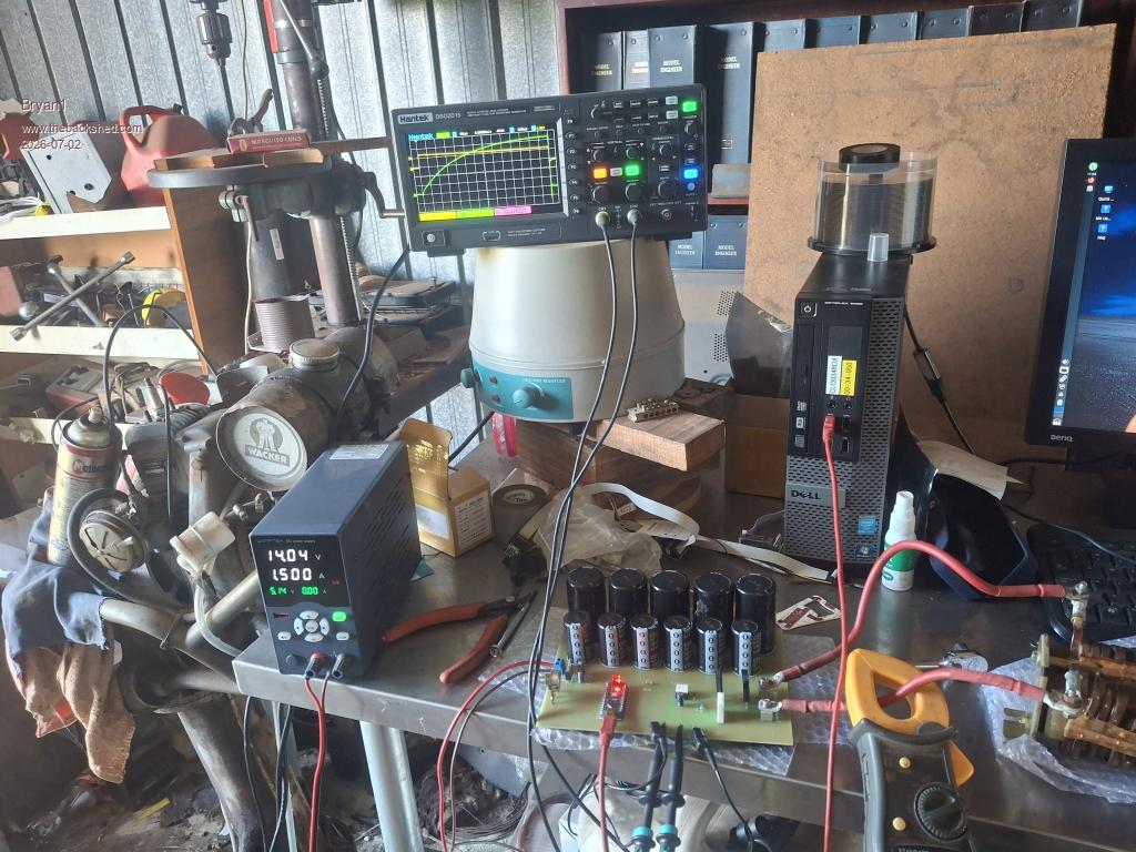 Now just had to go that bit further  and we finally got a voltage drop on the power supply, the current on the clamp meter was 4.1 amps. and we finally got a voltage drop on the power supply, the current on the clamp meter was 4.1 amps.Regards Bryan |
||||
| KeepIS Guru Joined: 13/10/2014 Location: AustraliaPosts: 2182 |
Unfortunately the current clamp meter is not fast enough to read anything meaningful with an xxus pulse, the same with the Power supply, and especially if the supply is sitting across the large value of Capacitance on the Sat-tester board. NANO:Inverter V 8.2ks - Linux AvrDude GUI script V4.1 |
||||
| Bryan1 Guru Joined: 22/02/2006 Location: AustraliaPosts: 2122 |
Ok I had a bit of look at these 40mm green toroids with a yellow top and the AI on google said it's more than likely it a T-26 powered iron core suited for chokes among other things So glued 5 of them together as I do have 10 of them so a pair can be made and put 5 turns of 7mm diameter wire thru. 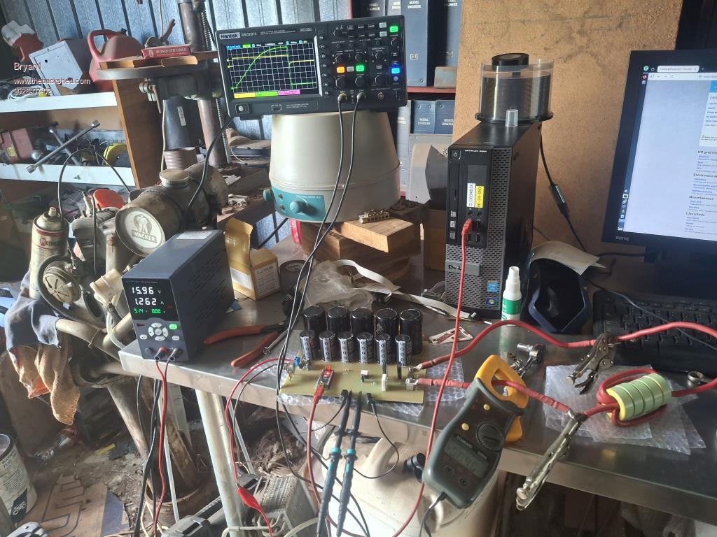 Now the current ramping up on each adjustment of the pulse it's not in my opinion going into saturation as the sense is still rising now going a wider pulse does make the sense trace drop off so one would think thats is the saturation point. |
||||
| Solar Mike Guru Joined: 08/02/2015 Location: New ZealandPosts: 1219 |
Another way to measure this is wind on say 30 turns of approx 1.5mm wire and do your test, starting at the narrowest pulse it will output. Having more turns allows the core to saturate at a lower current, and not allowing your capacitor voltage to drop off, showing as a roll off droop on the scope display. You should be getting scope output like @nickskethisniks posting, with a rising curve, not a drooping one. Once you know the saturation current with 30 turns, then the saturation level per turn on the core is your reading X 30 = Isat. From that measurement, if the core requires say 5 turns to get your wanted inductance, then the max saturation level would be Isat/5 etc. Cheers Mike |
||||
| Bryan1 Guru Joined: 22/02/2006 Location: AustraliaPosts: 2122 |
Well looking at the scope figures for the T 26 iron core trial 6.8 volts rise on the sense trace is 6.8/0.02 = 340 amps Now for the inductance 15.96 x 0.0005/340 = 23.47uh |
||||
| nickskethisniks Guru Joined: 17/10/2017 Location: BelgiumPosts: 481 |
Sorry if my writing is a little bit hard, only good intensions here, I'm finding it verry interesting from an engineering point. In my "feedback" I was a little bit to fast in responding to meassure the cap voltage wich in your case is not that interresting at all as your current sense is eating away your voltage across your inductor with high currents. The real voltage across your inductor is in fact cap voltage minus track loss, sensor loss and mosfet loss. So in a way you need to bring this in account while calculating your inductance. The difficulty is that losses go up in time/with higher current. Mike suggested to increase the amount of turns arround the core wich would result in less current and voltage drop over all components wich will increase accuracy. The real inductance will probably be a lot lower since you have not 16V across the inductor. Edited 2026-07-02 16:01 by nickskethisniks |
||||
| Bryan1 Guru Joined: 22/02/2006 Location: AustraliaPosts: 2122 |
All good Nick this is a learning curve for me so all information is welcome, now with testing the big aero-sharp choke Poida did do the test on the one he had and got the same result.Now with that T 26 powdered Iron Core the sense trace was less curved and alot higher when doing the uS steps and comparing the 2 tests the T 26 won hands down where in fact it did go longer on the us pulse before breaking down. Ok from a newbie's perspective the capacitor voltage will be the same as the supply voltage wouldn't it as feeding DC into the capacitor is tied to the voltage. Or with this tester is my idea all wrong. |
||||
| nickskethisniks Guru Joined: 17/10/2017 Location: BelgiumPosts: 481 |
Yes, that holds true, supply voltage is capacitor voltage. But the the voltage you should actually use in the calculations is the voltage over the inductor. So while at 0A there is in fact the complete 16V over the inductor. But at 100A it is more like 16V - Rdson*100A - Rshunt*100A - voltage drop across pcbtracks and wiring. You the more current the lesser voltage across the inductor. Allthough calculating with the voltage drop at the highest current in the test will also not give you the right inductance. As long as the core is not saturating and the ramp is lineair you can half the voltage drop to calculate the inductance. This will only be true for ferrite (hard saturation), for iron powder or sendust you probably need to take 2 points at the slope and take the average for a good measurement. You still follow?  |
||||
| Bryan1 Guru Joined: 22/02/2006 Location: AustraliaPosts: 2122 |
Ok just ran a test and measured the voltage on the upper choke connection and found the difference from the power supply to be 0.2 volts lower when the 500us pulse was going so basically deduct 0.2 volts from the measurement taken. |
||||
| Bryan1 Guru Joined: 22/02/2006 Location: AustraliaPosts: 2122 |
I must admit since I have got that Induction Tester finished and working I'm very happy with what I'm seeing with the inductors I have made and seen the one I made this morning out perform my aero-sharp one So the mornings job is stripping the wire off those last 5 green toroids gluing them together and then the hunt in my wire pile to find more 7mm diameter cable to make the second choke. Doing a search on my Temu induction project did produce the schematic I put on the first post as somehow I did think I would need it again which has rung true.I did get 5 of those big dual ultrafast diodes so one of them will do also with that bank of 20 off 0.47uf 250 volt capacitors I'm nearly there to making my induction heater. Regards Bryan |
||||
| nickskethisniks Guru Joined: 17/10/2017 Location: BelgiumPosts: 481 |
Based on the measured value, you referenced the measurement from gnd at the input? Don't forget your shunt is in the gnd path and you now only measured the drop in the positive rail, if you did the measurement with the scope. When dealing with short duration pulses the dvm is to slow and you should do this with the scope. You want to measure the voltage across the inductor itself. Now you need to be carefull doing this. As your ground clips of the scope probes are electrically joined together in the scope you need to be carefull not make shorts, the ground clips should allways be connected to eachother, for this task you need differential probes. For now I would just calculate it based on the resistance of the components. Or probe 1 connection of the inductor and the other connection with another probe referenced to ground, then you substract the lowest value of the highest value, this is then the voltage across the inductor. Edit, Yes you can be happy with the result. It will surely give you a good platform to see differences between the inductors you allready made or having arround. Edited 2026-07-02 17:33 by nickskethisniks |
||||
| Bryan1 Guru Joined: 22/02/2006 Location: AustraliaPosts: 2122 |
Nick I only have a 2 channel scope as thats all I thought I would need and bang for buck it has served me well building my first inverter. Now my Induction Tester is made from Poida's schematic and I'm sure he thought of all these considerations beforehand. For the voltage drop measurement yes I did use my DMM and I'm thinking of setting up my old Fluke 865 scope meter which can give me the frequency etc and even graph it using the scope view. The ground point I used was off one of the scope probe grounds which is on the 0.02ohm resistors path so I'm sure that voltage drop was taken care of. Now doing that iron core test today does prove it rocks over the big aero-sharp choke but in saying that aero-sharp choke did pass the pub test and will be fine for that inverter I made it for. |
||||
| KeepIS Guru Joined: 13/10/2014 Location: AustraliaPosts: 2182 |
Ferrite E-core and Sendust toroid core saturation curves. Yellow Trace: Isolated 500A Hall effect Current Sensor output, rated to 700A but peaks around 1200A with good accuracy. Tested against a High current resistive Shunt - to over 1000A and virtually identical, but without any noise. Test voltage 100V. Vert div = 175A per division. No shunt Resistor, using the high current Hall effect sensor above. For reference, a 1-ohm resistor in place of the choke - 1400A. 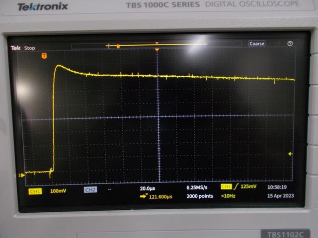 16uH Ferrite E-core choke, gaped and 4 turns: 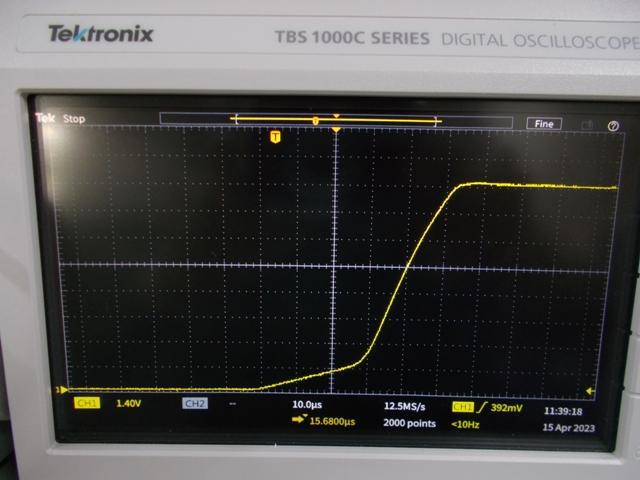 37uH 10 stack toroid test choke 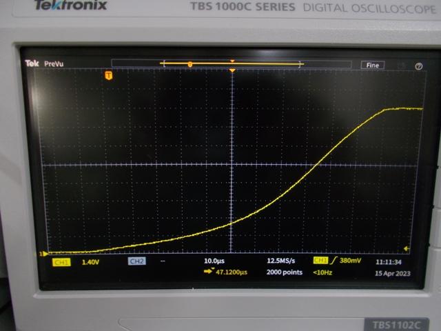 Quick overlay of the two chokes curves above, see the abrupt saturation point of the gaped E-Core at just above 175A. Keep in mind that the E-Core started with less than half of the inductance of the large test stacked toroid ring core. 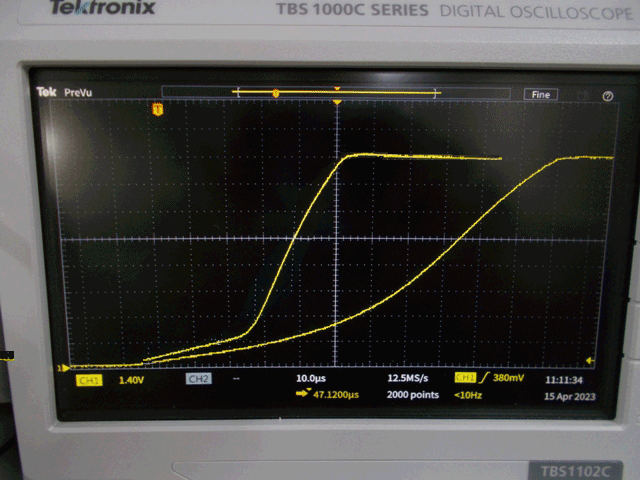 . Edited 2026-07-03 18:34 by KeepIS NANO:Inverter V 8.2ks - Linux AvrDude GUI script V4.1 |
||||
| The Back Shed's forum code is written, and hosted, in Australia. | © JAQ Software 2026 |
