| |
  Page 3 of 3 |
| Author |
Message |
johansen
Newbie

Joined: 01/08/2014
Location: United StatesPosts: 13 |
| Posted: 12:21am 16 Oct 2026 |
 Copy link to clipboard |
 Print this post |
|
I did some measurements today with a APC smart ups rated for 700watts/1000va but i have the larger transformer from the 1000w/1400va ups in it.
Both the yellow and purple traces are 2000:1 current sensors into an 11 ohm resistor, into a 1x o scope probe.
Yellow is a current transformer, purple is an LEM closed loop sensor rated for 300 amps.
This particular ups is much better than a few others i have played with, some are so bad on the dc current into the primary that the output voltage waveform is clipped flat on the side that's saturated.
As for the pwm frequency on these UPS's, it varies depending on how much inductance you insert into the primary or secondary. by default there is none, i have a rather large inductance inserted
The last photo in the imgur link is the current flowing with a 60 watt soldering iron for a load, which is controlled by a triac.
I measured a filtered, 14mv dc offset peak today, which corresponds to 2.5 amps of dc flowing, which is enough to come close to saturating the transformer in my opinion. again, this ups is better than average.
https://imgur.com/a/transformer-offset-currents-5onZNmD
EDIT: i have added two more images. I wrapped the transformer secondary through the lem sensor 7 times which almost perfectly cancels out the ac current. its not a fixed dc current, i'm able to manipulate it buy turning a load on or off.
So anyhow as for how long it takes to saturate the transformer from a given voltage, that is going to highly depend on what flux density you run and the permeability of the core, with toroidal inductors being very high.
I measured 400mh inductance for the 240 winding on this 65 pound transformer:
https://imgur.com/a/6kva-isolation-transformer-mqGhHAy
my inductor design spreadsheet is suggesting to get 400mh from 164 turns on that core, requires a permeability somewhere around 2500 with a 0.05mm air gap. or a permeability of 2000, with zero air gap.
This results in a flux density of 1T with a current of just 1.2 amps (200 amp turns)
so when we try to calculate how much time we have before 1 amp flows, well if the voltage potential is 400mv, then the current rises at 1 amp per second. 400mv corresponds to basically 0.1% of a 400volt peak to peak system.
Decreasing the inductance by inserting an air gap allows for more dc current to flow, but the current rise time will be inversely faster for the same voltage offset.
Edited 2026-10-16 11:30 by johansen |
| |
poida

Guru

Joined: 02/02/2017
Location: AustraliaPosts: 1494 |
| Posted: 12:51am 17 Oct 2026 |
Copy link to clipboard |
Print this post |
|
how quickly does the toroid go into partial saturation after I switch the diode in circuit?
using the standard test conditions (200W load)
we can see here:
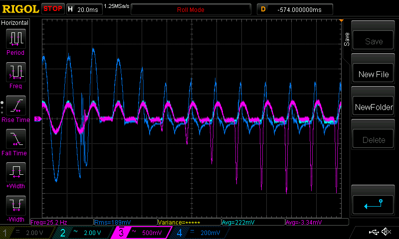
it takes about 9 50 Hz cycles to be stable in it's new running state.
This is an interesting experiment to do, in my view.
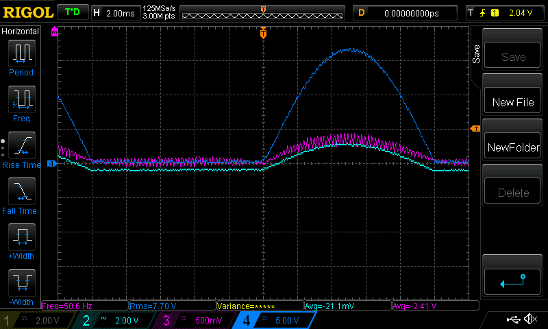
Dark Blue is AC volts (about 240V AC RMS)
Purple is primary current
Light Blue is secondary current
Past tests have shown DC input voltage is quite stable so no need to
probe that any more.
here is one cycle with the diode in circuit using the new probe locations.
I was wondering what the secondary current would look like
and so here it is.
Zero crossing of AC output is at one division in from both the
left and right side of the capture.
Both current signals are now AC coupled, this must be kept in mind.
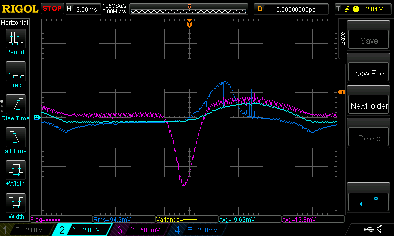
wronger than a phone book full of wrong phone numbers |
| |
poida
Guru
Joined: 02/02/2017
Location: AustraliaPosts: 1494 |
| Posted: 03:23am 17 Oct 2026 |
Copy link to clipboard |
Print this post |
|
I am not have much luck with current sensing right now.
But the idea of using an asymmetric waveform to reduce the problem does work
as shown below:
Dark Blue is AC volts on secondary
Light Blue is AC current on secondary
Purple is primary winding current
this is normal, i.e. no diode in circuit
it runs quiet too
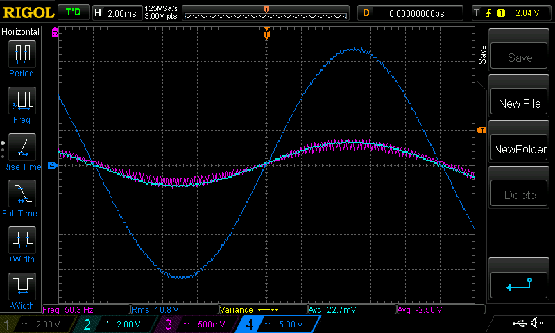
next is with diode in circuit.
a solid hum from the toroid.
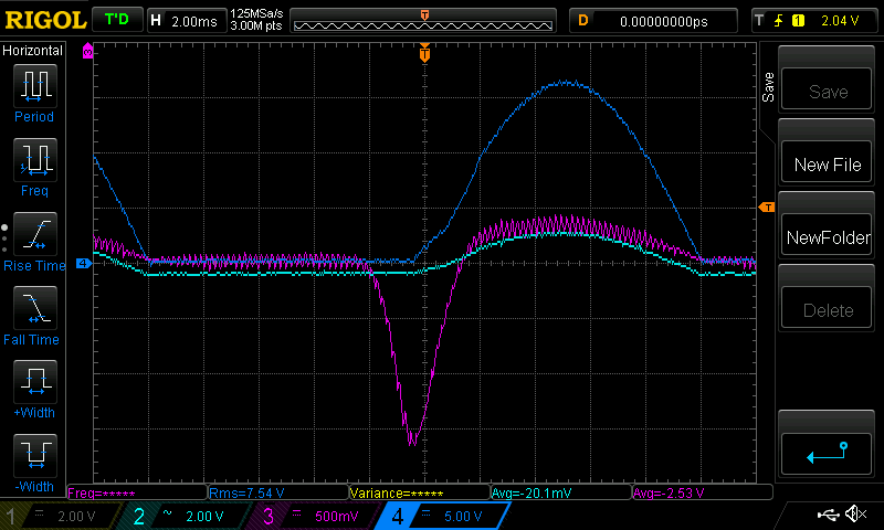
And this is with 3.5% less amplitude on the 1/2 wave where the diode
does not conduct (and zero AC current, zero AC voltage)
This is a result. The toroid is back to being very quiet too.
There was no closed loop control with the waveform symmetry
just a fixed value.
Now, on to getting a solid signal from the current sensor..
wronger than a phone book full of wrong phone numbers |
| |
poida
Guru
Joined: 02/02/2017
Location: AustraliaPosts: 1494 |
| Posted: 06:04am 17 Oct 2026 |
Copy link to clipboard |
Print this post |
|
And I now have a closed loop control running.
it is not PID, only "bang bang" but it works.
see
https://youtube.com/shorts/BYY4eldyFOA?feature=share
I have the closed loop control already running with no load.
it is stable.
then I twice switch in the 200W load with series diode.
You can see it stablise under this load and then stablise with no load.
I then disable the closed loop control via an external switch.
And then twice switch the load to show what no control results in.
The current sensor output is rather noisy so I use a 100Hz at -3db RC low pass filter,
(0.1uF and 15K resistor). This delays the signal about 24 PWM clocks.
I am running code that looks only at the primary current at both zero crossings
and altering one or the other 1/2 wave to suit.
wronger than a phone book full of wrong phone numbers |
| |
wiseguy

Guru
Joined: 21/06/2018
Location: AustraliaPosts: 1326 |
| Posted: 02:10pm 17 Oct 2026 |
Copy link to clipboard |
Print this post |
|
The results are sounding promising. It appears you are monitoring the output AC voltage after the diode you insert ?? If it's intentional, I don't understand why it is being monitored there - the AC waveform shape helps us to see saturation distortion level etc ? Maybe there is a point here I'm failing to see...
If at first you dont succeed, I suggest you avoid sky diving....
Cheers Mike |
| |
analog8484
Senior Member

Joined: 11/11/2021
Location: United StatesPosts: 241 |
| Posted: 06:04pm 17 Oct 2026 |
Copy link to clipboard |
Print this post |
|
Kudos on the results so far. The video certainly looks like encouraging results but the AC voltage does look like it's from after the diode. Just assuming it's for clear demo purposes and the Vfb is still coming from the inverter output cap before loads.
I like the new control loop changes. In particular, the 2 separate control loops and the imbalance loop only reduces the unloaded/under-loaded half wave based on current imbalance without dependencies on waveform attributes (e.g. peaks). This should be more robust under real-world load conditions where potentially multiple loads are running that could make waveform attribute comparisons across the half waves less accurate for imbalance indication.
Look forward seeing more results for different test cases. Perhaps including the no load hum scenario?
Edited 2026-10-18 04:08 by analog8484 |
| |
| |
Page 3 of 3 |

 Notice. New forum software under development. It's going to miss a few functions and look a bit ugly for a while, but I'm working on it full time now as the old forum was too unstable. Couple days, all good. If you notice any issues, please contact me.