
|
|
Forum Index : Windmills : Need some help with mini windmill
| Page 1 of 2 |
|||||
| Author | Message | ||||
| jeen Newbie Joined: 06/07/2008 Location: Posts: 11 |
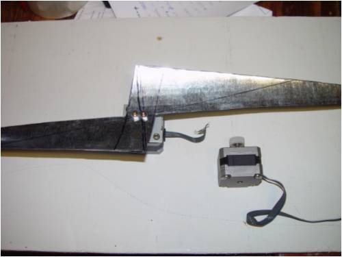
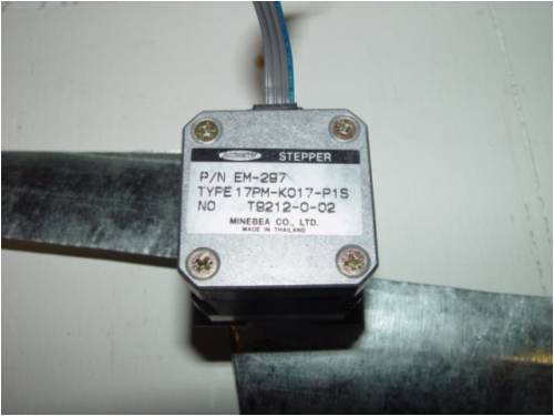
Hello fellow members, I just recently found/join this forum :) after trolling on thebackshed for a few days. There are so many projects that i would like to do but as a noob with no previous knowledge or experience, I thought i get my feet wet with the Mini windmill http://www.thebackshed.com/Windmill/assemblyMini1.asp I'v ripped out 2 stepper motors from my old epson printer and have so far made the props and mounted them on the motor. Im having problems with: 2 full wave bridge rectifiers 47uF 63volt capacitor Would someone please specify exactly which rectifier and capacitor im suppose to get? Iv been browsing on RadioShack.com and there are so many full wave bridge rectifiers and no 63v capacitor to be found  . .
Any advice and help would be much appreciated. Thanks |
||||
| Gizmo Admin Group Joined: 05/06/2004 Location: AustraliaPosts: 5182 |
Hi Jeen As the Minimill is a low power unit, the capacitor values are not at all important. The uF value could be anything from 10uF to 100uF. The voltage of a capacitor is the safe operating voltage, so any voltage over, at a guess, 24volts, would be fine. So if you find a 33uF 32v cap or a 10uF 160v cap, they will both work fine. Those values on the circuit diagram were what I found in my junk box of spare parts at the time. For the bridge rectifier, just use the cheapest you can find, again its all low power stuff so anything you find will do. Welcome to the site Glenn The best time to plant a tree was twenty years ago, the second best time is right now. JAQ |
||||
| jeen Newbie Joined: 06/07/2008 Location: Posts: 11 |
Thanks Gizmo. Cant wait till radioshack opens in the morning :) |
||||
| Dinges Senior Member Joined: 04/01/2008 Location: AlbaniaPosts: 510 |
This rectifier would be more than fine (is, in fact, overkill, but is still the smallest and cheapest I could quickly find): Radio Shack part nr. 276-1152 A suitable electrolytic capacitor: Radioshack part. nr. 272-1044 BTW, my favourite electronics store is junked pieces of home electronics. An old defect PC power supply will have all the components you'd need. For free. As you can see I'm not just cheap but lazy too. Though I think 'thrifty' sounds nicer. Don't forget to report back in here with your contraption when it's finished. |
||||
| Dinges Senior Member Joined: 04/01/2008 Location: AlbaniaPosts: 510 |
(/me slaps forehead ) If you've taken that printer apart for its stepper motors then maybe you still have the printed circuit board (PCB) with all the electronics on it ? There's bound to be at least one suitable rectifier on it, and plenty of electrolytic caps. Who needs Radio Shack anyway...  |
||||
| brucedownunder2 Guru Joined: 14/09/2005 Location: AustraliaPosts: 1548 |
Hey,, Dutchy,, how ya goin ??. Please come back to the irc ---- Bruce Bushboy |
||||
| jeen Newbie Joined: 06/07/2008 Location: Posts: 11 |
Dinges, Thanks a bunch for those part numbers. Im not much of an electrical guy, infact I dont even know what to look for on that circuit board :( I got 2 green thumbs and its got NOOB writen all over it 
but ill go look over that pile of junk just in case :) Thanks again |
||||
| jeen Newbie Joined: 06/07/2008 Location: Posts: 11 |
Ok iv taken off the pcb and this is what i see as far as capacitors go: 560uf 200v 1000uf 10v 3500uf 50v 330uf 6.3v 220uf 35v Can any of these be used? I dont see anything that looks like a rectifier tho. |
||||
| Dinges Senior Member Joined: 04/01/2008 Location: AlbaniaPosts: 510 |
Hehehe... Radio Shack is not going to like this... The 560u/200 V; 3500u/50V and 220u/35V are suitable candidates. Basically, anything with a working voltage of more than 35 V and a capacity of over 47 uF should work here. As for rectifiers: try to look at the spot on the PCB where the 560 u/200 V (large) capacitor came from. Nearby should be either: 4 separate diodes, used as rectifier (black plastic cylinders with white circle over one end), or a black plastic flat thingy with 4 legs. Two legs will be marked with a '~', these are the AC inputs. The two other legs will have a '+' and '-' marking. That's the rectifier. But, you need two rectifiers; the printer board may have only one (or even just diodes, which can be used as rectifiers too). So even if your printer board has just one you may still need to go out and buy a 2nd one. Or, use diodes wired as rectifier (a rectifier bridge is just 4 diodes wired together and in one housing anyway). Alternatively, make a good picture of the PCB (esp. the part where the 560u/200V capacitor came from) and maybe we can hunt the rectifier down... Bruce: I'm regularly in Ross's IRC nowadays. Feel free to hop in sometime. |
||||
| jeen Newbie Joined: 06/07/2008 Location: Posts: 11 |
Heres some pics 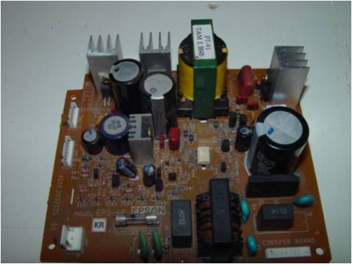
I ran over to the local radioshack earlier today. The sales associates are as helpfull as a block of wood on a rainy day  I rather order the stuff online and pay for shipping then frequent that store again. I rather order the stuff online and pay for shipping then frequent that store again.
|
||||
| Robb Senior Member Joined: 01/08/2007 Location: AustraliaPosts: 221 |
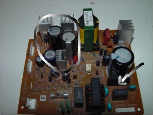
Theres a bridge rectifier with the arrow and there will be diodes that you may be able to use in the circle. That big bridge is way overkill but you'v got it so use use it.
Oh is that a blowen fuse on that board? I hope the bridge isn't shot. |
||||
| Dinges Senior Member Joined: 04/01/2008 Location: AlbaniaPosts: 510 |
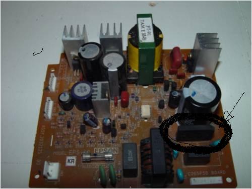
The rectifier is that flat rectangular plastic block, with the circle around it and arrow pointing to it. Close to the large electrolytic capacitor. Verify that it has 4 legs, 2 marked with '~', one with '+' and one with '-'. Now, if you can scrounge an old PC powersupply, in there (again close to the one or two large electrolytic capacitors) you'll find a rectifier too. As far as Radio Shack goes: Gee... You're the first one I've heard say such things about that store with its large inventory of electronics parts and knowledgeable  sales persons. By now you likely know more about electronics than the staff... sales persons. By now you likely know more about electronics than the staff...
BTW, before you toss those PCBs in the garbage, at least remove the aluminium cooling fins and the associated 3-legged components, which likely are FETs, rectifiers and/or voltage regulators. Remove the fuse and the white thingy in the middle (with 6 legs, an optocoupler) too while you're at it. It may come in handy in the future if you decide to play around more with electronics. |
||||
| Robb Senior Member Joined: 01/08/2007 Location: AustraliaPosts: 221 |
Opps looks like we where both typeing at once  |
||||
| jeen Newbie Joined: 06/07/2008 Location: Posts: 11 |
Sweet 1 rectifier down :) Gonna see if i can locate another one in my shed. The guy at radio was horrible, not customer friendly at all. I walk in there and started to look for items on my list. The guy never comes over and ask if i needed help. I go over there to him (he was free and scratching his behind) hand him my list of items. He looks up 1 item and hands me the list back and says "we dont have it". Not even, "can we order it in for you?" "I can have it in here in so many days" Guess he didnt need my business. Thanks again Dinges ps the fuse is fine, not blown |
||||
| Robb Senior Member Joined: 01/08/2007 Location: AustraliaPosts: 221 |
There is probably enough diodes on that board elsewhere to build another bridge. |
||||
| jeen Newbie Joined: 06/07/2008 Location: Posts: 11 |
hey Robb, you got a link or diagram on how to make that bridge with diodes? |
||||
| Dinges Senior Member Joined: 04/01/2008 Location: AlbaniaPosts: 510 |
Robb is right, there will be enough diodes on that board to finish your project. But it's harder to explain where to find the diodes on that board, hence if you can quickly/easily find a rectifier, I'd go that route. If you want to use plain diodes, there's your schematic: http://www.thebackshed.com/Windmill/assemblyMini3.asp Each black triangle-with-stripe is a diode. 4 of those combined in one house is called a rectifier. Yes, it's as easy as that :) Ok... How to find suitable diodes on your PCB... First, if you can, make a good close-up photo of the brown circuit board, especially the left-middle part with all the many small components. You're looking for tiny glass components with two leads. Likely, the circuit board will be marked (in white lettering) with text as 'D102', 'D302', etc. The 'D' indicates diodes here. The glass diodes may be printed with *very* fine lettering, for example '1N914' or '1N4148'. Others have colour bands (for example, yellow-brown-yellow-grey = 1N4148). These would be fine for your application. But, basically, any old diodes you'll find in there should work (provided it's not a zener diode, marked 'ZD...'). If you can't find them with the above explanation or the help of Robb, post another good detailed picture and maybe we can hunt some suitable diodes down. BTW, you may want to read this too: wikipedia 'diodes' Here's what your diodes should look like: http://en.wikipedia.org/wiki/Image:Diodes.jpg The problem is some of these glassy thingies look like plain diodes but are in fact 'special' diodes, not best suited for this application of rectifying. Zener diodes, for example. Anyway, by now you should have an idea of what you're looking for on that circuit board. If the white lettering near the component says 'D123' you can be sure that it's a diode. Now, there should be a 'band' printed on the diodes. The band is the vertical stripe at the tip of the triangle in the schematic. Diodes have polarity, i.e. it matters how you wire them up. Anyway, that's the reason I'd suggest trying to find a rectifier if you can; basically because it's easier. But, there's no reason diodes won't work. In fact, I just recalled that a few years ago, long before I found these discussion forums, I made something just like it: a stepper with rectifier (and voltage regulator). The rectifiers were made out of plain diodes (1N4148 in my case). Lousy picture can be found here: http://www.anotherpower.com/gallery/dinges/stepper_generator _resized The 8 diodes are so small you won't be able to see them in this bad picture. But, it works, and should work for you too. edit: it looks like there are some suitable diodes near the large transformer (large yellow thing at the top). I'm talking of the 2-leaded black cylindrical things with a white band at one end. Those are diodes too. If you can find 4 of them you'd have all the parts you need. |
||||
| jeen Newbie Joined: 06/07/2008 Location: Posts: 11 |
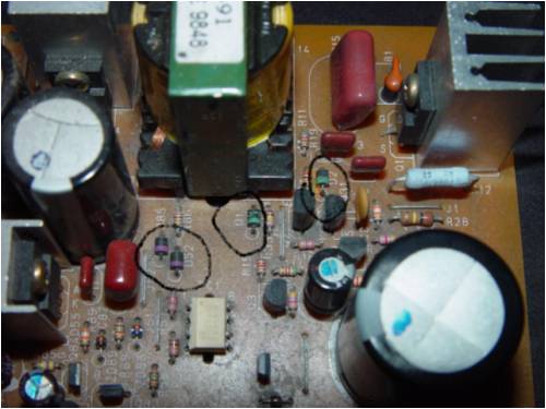
I hope those are diodes but I seem to have a problem. Theres 3 purple striped and 3 teal striped ones. Can they be mixed and matched? 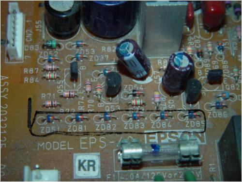
I take it those are the zener diodes? 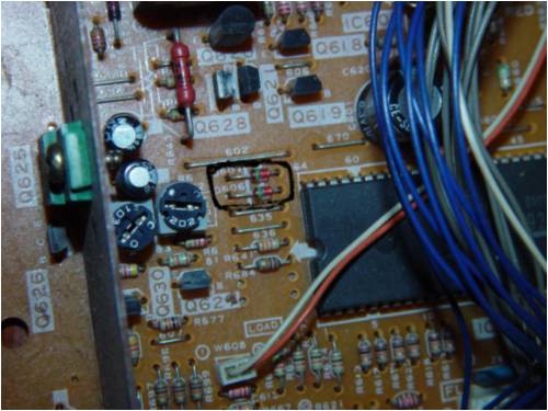
this is from an old vcr that i just took apart. Unfortunately there dont seem to be any rectifiers but there are more then 8 of those diodes. btw are the strip an indicator of where the arrows point? |
||||
| Dinges Senior Member Joined: 04/01/2008 Location: AlbaniaPosts: 510 |
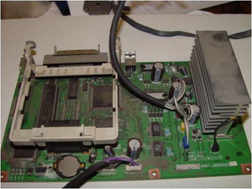
The 3 purple and teal (just learned a new word) diodes in your first picture should work fine, even when used mixed. Not much of an issue in your particular application. The 6 zener diodes in your next picture shouldn't be used, just as other zener diodes in that same image. Zener diodes are used for voltage stabilization/regulation, not rectification. The last picture from the VCR, with the two (or eight) green diodes should work fine too. BTW, if you look carefully at the white print under those diodes, you'll see the symbol of a diode: a triangle with a line at the tip. Notice how that line is at the same side as the black and/or green band around the diode. I'm 100% convinced that there is a normal rectifier (4-legged one) in that VCR too, just as in the powersupply of the printer. Have a closer look at the circuit board where the 220/110 V power enters and where the fuse is. Near the fuse should be a large capacitor and in that vicinity there should be a rectifier too. Just to give a hint on where you should be looking. Now you see that those old discarded circuit boards are a veritable goldmine of components ? Consider them your very own Radio Shack, without ignorant moody sales persons and exorbitant prices. No shipping costs either. 
edit: on 2nd thought, there's a small chance that the 2 diodes in the VCR picture are zener diodes too. Hard to tell from the picture, but if you remove one of the diodes and look at the symbols on the print, it should not look like this symbols zener diode . There's actually a 3rd symbol for zener diodes but I can't seem to quickly find an online image of it. Anyway, as long as the printing under that green diode in the VCR looks just like the normal symbol of a diode it should be fine. But, if I were you, I'd try to find the rectifier on the power supply board. Easier to use (and more of a challenge to find...) And to answer your final question: yes, correct: diodes |
||||
| jeen Newbie Joined: 06/07/2008 Location: Posts: 11 |
No luck on the rectifier from the vcr power board. There are 4 huge diodes wired next to the transformer though. Might be more of a learning experience and fun for me to build the 2 rectifiers :) I have learned quite a bit in the last day or 2. Thank you very much Everyone. |
||||
| Page 1 of 2 |
|||||
| The Back Shed's forum code is written, and hosted, in Australia. | © JAQ Software 2026 |
