
|
|
Forum Index : Windmills : 36 slot stator and a long way to go...lol
| Page 1 of 4 |
|||||
| Author | Message | ||||
CraziestOzzy Senior Member Joined: 11/07/2008 Location: AustraliaPosts: 152 |
G'day from a newbie. I am keen to make my own multi-purpose brushless generator. I aim to have wired into the stator slots about three sets of wiring configurations. Each configuration will have its own unique number of turns and wire gauge. One config will be wired for high amps and low voltage. Second config will be wired for low amps and high voltage. Third config will be used to run a low RPM high torque motor. Each of the three configurations of wiring will have its own separate wiring loops and electronic (passive components) controls. The electronic controls will basically incorporate relays and temperature, voltage and amperage monitors. But more on this part in later weeks. My current question (problem  ) is focussed on the ideal setup for a low RPM generator as far as magnets are concerned and a matching wiring config that is suited to four phase setup. By low RPM, I mean around a 1000rpm or less. I can settle for more or less phases, depending on what would work best. ) is focussed on the ideal setup for a low RPM generator as far as magnets are concerned and a matching wiring config that is suited to four phase setup. By low RPM, I mean around a 1000rpm or less. I can settle for more or less phases, depending on what would work best.
I like the idea of using neo magnets but dislike their intolerance to temperatures above 80 - 100 degrees centigrade. The high temperature tolerant neo magnets 100 degrees and over I am unable to locate as far as a supplier goes. So I am looking at using the "ceramic" magnets. I could use neo magnets if I work on methods for reducing or removing heat. I intend to use the largest ceramic magnets that I can fit onto the rotor and aim to use iron laminations to surround and affix the mags to the rotor as well as enhance those good magnetic "vibrations" towards the stator  Issues of cogging will be dealt with later. Issues of cogging will be dealt with later.
I am at a loss as to how many poles I should be looking at for the rotor. I like the idea of a four pole setup as it allows me to use large blocks of ceramic magnets. I also am questioning if an eight pole rotor would be better than a four. Each of the three individual wiring configurations mentioned earlier, will obviously have their own unique pole sets within each of the four phases, to comply with the number of poles I will eventually decide on for the rotor. Your ideas and thoughts and critic will be much appreciated and some useful links to similar large motor-generator rebuilds would be great...I have heaps of stuff bookmarked and a few more won't hurt 
Better stop here before I get sum of you gurus lost. My specs for the stator are: 1) each stator slot can hold 52 wire strands of 1mm thick (18AWG) wire loosely packed by hand. 2) I calculated the area squared for each slot is 126mm squared. 3) The length of each slot is 110mm long and I have a total of 36 slots...allot of wire 
4) With an air gap of around 2mm between the stator and rotor, the diameter of my yet to be built rotor will be 138mm. My intended use for this generator will be to use wind, solar and another motor as the force to drive my baby. I can use all three energy sources at once (within control of course) or have one source working and the other two disabled with the inactive outputs being drained into some nice peltier units. I have just started this project and intend to post my failure or success as well as my progress and thoughts  ...so here is the start and I finish my opening post here: ...so here is the start and I finish my opening post here:
This is the A.E.I. Engineering motor I am working on. It was a dual delta and wye setup. 1435rpm, 7.5 horses and 10.8 amps. 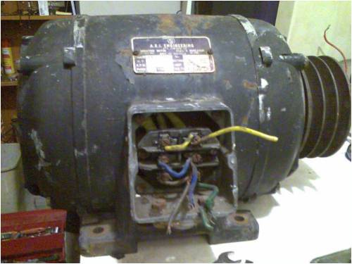
This is the removed rotor...the 30cm ruler is a good scale indicator. 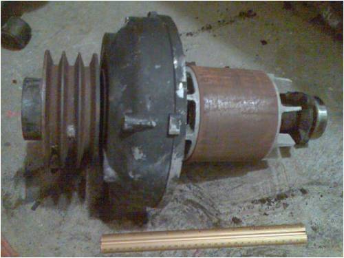
Removing the old wire was very much a pain. The insulation was deteriorated and flaking in parts, so I removed it all. Wood was actually used to peg the wire into the stator slot...bigger pain. You can see here the second layer of wire shielded from the first with some insulation. 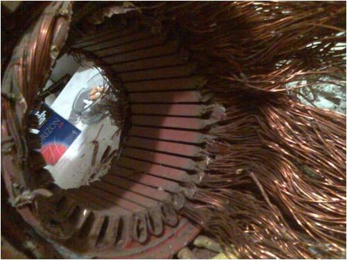
All the wire gone after a full day of work...lots of coffee breaks...the calipers are set at 110mm, which is the length of the stator slots. The inner diameter of the stator is around 140mm. 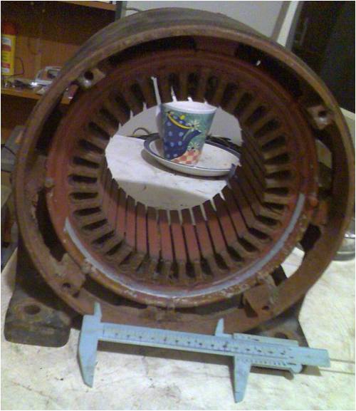
http://cr4.globalspec.com/member?u=25757 http://www.instructables.com/member/OzzyRoo/ |
||||
harrisvs Newbie Joined: 11/07/2008 Location: GreecePosts: 1 |
hi this is Harris from Greece.Why you didnt burn it first.How many poles you want to rewind this motor. harris |
||||
| CraziestOzzy Senior Member Joined: 11/07/2008 Location: AustraliaPosts: 152 |
I did think of burning or using flame to make life easier, but did not want to destroy the insulation between the laminations. I am suffering "writer's block" as to how many poles would be ideal on the stator in relation to the desired number of phases...treating each of the three configurations individually is not a problem regarding this. I mentioned the idea of having four poles on the rotor with huge ceramic magnets or eight poles with smaller magnets. http://cr4.globalspec.com/member?u=25757 http://www.instructables.com/member/OzzyRoo/ |
||||
| Dinges Senior Member Joined: 04/01/2008 Location: AlbaniaPosts: 510 |
Will be an interesting project. I'm curious: how many poles did that motor have originally (or, what was its RPM) ? There seems to be very little backing iron so I'm guessing at an 8-pole, perhaps a 6-pole. (edit: my mistake, after re-reading your post I see it's 1435 RPM, thus 4-pole. Strange. Would have expected much more backing iron) The rotor is stubbier (shorter and larger diameter) than my 10 hp conversion (which was originally a 4 pole motor). So your motor seems to be more suited for conversion to a slow-running generator than mine. Designing a generator for just one purpose (wind) is difficult enough as it is, frought with compromises. Building a generator that would be suitable for 3 different drivers would be even harder and need even more compromises. I don't think I'd use ceramics, as they're much larger than NdFeB magnets and weaker. I agree with your analysis of the temperature sensitiveness of NdFeB magnets. It's the one thing I dislike about the magnets I'm using in the 10 hp conversion, they're standard temperature grade (I originally bought them a few years ago to build an axial flux). Next time I would buy different magnets: - H, UH or SH temperature grades - not nickel coated but epoxy coated (better adhesion when glueing them to the rotor) - with countersunk holes for attachment/locating while glueing them. Such magnets are for sale over here: (http://web.telia.com/~u41124251/Block.htm (not affiliated, just a satisfied customer) Next time I will definitely try to purchase magnets with the above characteristics or have them custom-made in China if need be. It's good you didn't toss the stator in the fire. Motor rewind shops use temperature controlled ovens (within strict temperature limits) to 'roast' the varnish over a several hour span. Too high temperatures can damage the laminations and distort the motor house. The consequence would be higher stator losses. In fact, sometimes it's required that a rewinding company performs a stator-loss test after burning out the coils, to verify that performance of the stator hasn't been degradated by the session in the oven. Without knowing exactly what you want to do with this motor/generator it's hard to give advice on pole numbers. 12 pole should be technically doable though, I think. For anyone to be able to help you, you'd need to supply at least the intended system voltage and cut-in RPM. I don't see any reason for using a 4-phase arrangement (which is in reality 2-phase, with a phase shift of 180 deg. between 2 of the 4 phases). 3-phase is normal, I can't think of any reason to deviate from this. And yes, removing the copper out of the stator takes the better part of a day or two. Not my idea of fun. |
||||
| CraziestOzzy Senior Member Joined: 11/07/2008 Location: AustraliaPosts: 152 |
Cheers and thanks for the link Dinges. I suspect the number of poles may have been eight or even more...was hard to really tell as the wiring was looped around every eighth slot, with a new run created at the adjacent slot until the entire stator was filled...much like an overlapping torus stator. The config for delta and star was created by strategic cuts and rejoins on either side of the stator and I couldnt see clearly what was going on through all the insulation. The RPM of the original motor was 1435rpm. I intend to focus on using this as a low RPM generator, if I can create the three different configs (or two at least) I would have a happy bonus. Intended voltage output would be 40 volts DC (maximum) at 20 amps max and also have another second config outputting 240 volts AC at a max of 10amps. I will likely just experiment with wind as the wind up here in Townsville is not the best for nine months of the year. I like the idea of using a twelve volt battery to start up a high torque low RPM motor (much like a roller door motor or car starter motor if need be) that would be attached to the generator along the rotor shaft to run it and disconnect the battery when the specs are reached for output of the generator be sufficient to run the attached motor...I wasn't going to mention this as yet as I have not been able to find much info on a "self running" generator...  ...I have not reached that point yet but my entire evil plan will hopefully run a marine fish tank 24/7 and any extra juice is a bonus. ...I have not reached that point yet but my entire evil plan will hopefully run a marine fish tank 24/7 and any extra juice is a bonus.http://cr4.globalspec.com/member?u=25757 http://www.instructables.com/member/OzzyRoo/ |
||||
AMUN-RA Senior Member Joined: 10/03/2007 Location: AustraliaPosts: 144 |
hey co where in town ru Every day the sun shines & gravity sucks= free energy. |
||||
| Jon Bennett Newbie Joined: 01/11/2007 Location: AustraliaPosts: 27 |
That is because it is not possible, every machine has an efficiency of less than 100% i.e. output is always less than unput. Interested to see how your mill along but as for a perpetaul motion machine i'm afraid that you are going to have a bit of trouble getting it to work. regards jon |
||||
| CraziestOzzy Senior Member Joined: 11/07/2008 Location: AustraliaPosts: 152 |
Yeah thanks John...I am not professing that I know too much with this project myself
I am avoiding the hype with "free energy" and "perpetual motion"
I am going to later upload a plan of the concept of attaching a motor with high torque and low RPM to the rotor shaft of my proposed low RPM generator. I am thinking as mentioned of using a battery to start up the high torque motor and then when the voltage and RPM's are right, the wiring I have looped in the generator will "kick over" and start running the motor. The other two or one config of looped wiring will then hopefully produce some voltage and amps for dring other stuff outside this system...working at a 100% efficiency is not a requirement, as long as I can produce some extra juice to be used outside the unit. If this idea is "pie in the sky", I will certainly discard it and move on to using wind and solar combo with perhaps a small fossil fuel motor for driving the rotor in the genny. http://cr4.globalspec.com/member?u=25757 http://www.instructables.com/member/OzzyRoo/ |
||||
| CraziestOzzy Senior Member Joined: 11/07/2008 Location: AustraliaPosts: 152 |
Up near the dam...I didn't know I had another local here? http://cr4.globalspec.com/member?u=25757 http://www.instructables.com/member/OzzyRoo/ |
||||
| Dinges Senior Member Joined: 04/01/2008 Location: AlbaniaPosts: 510 |
...it's pie in the sky... Overunity - though you don't explicitly called it that. Would be best to concentrate on things that don't violate the laws of physics and actually work, like wind and hydro. TANSTAAFL (there ain't no such thing as a free lunch). Sorry, at first I thought you were kidding about attaching a motor and a generator to the same shaft and having the motor drive the generator and let the generator power the motor (and ideally have some excess free energy left over for the fridge). I occasionally tell other people of that (and similar plans/'ideas') I have, but always in jest when I'm in a mischievous mood. Working above 100% efficiency WILL be needed for the plan to work. And efficiencies of >100% violate the known laws of physics. You'd be lucky to get 50% power out of the generator from the 100% of power you just put into the motor. Believe me... Lots of clever people in this forum who know about motors and generators. If it could be done, it'd have been done long ago in here and published widely for the benefit of other forum users. |
||||
| CraziestOzzy Senior Member Joined: 11/07/2008 Location: AustraliaPosts: 152 |
I had a little voice inside me that said all along that I need to put in over 100% for the idea to work...I might give the idea a go to see if I can get some juice left from the generator after using power to drive the motor after I have wired the stator and see what happens. I will though be focusing my efforts on wind, solar and fossil fuel motor to drive the generator and if at the end of construction I find I cannot attach my electric-motor-to-the-rotor idea to my "new" generator" I will discard the concept as a fallacy. Thanks for your thoughts...keeping me honest and on track http://cr4.globalspec.com/member?u=25757 http://www.instructables.com/member/OzzyRoo/ |
||||
oztules Guru Joined: 26/07/2007 Location: AustraliaPosts: 1686 |
It's not all doom and gloom, you will have a lot of fun along the way. You will learn lots of things that will make it clearer, and it's good clean fun. On an even brighter note: There are times when you can defy the laws of the known universe so keep your chin up. Such as when a fundamental particle goes through a decay cycle, it becomes a particle of less mass and a force carrier particle is created. (w bosun for these fundamental decays) So before the particle changes to another particle, an intermediate force carrier particle mediates the change to other particles..... where does this leave you? (you may ask). Well the mass of the force carrier particles and associated start and end position particles are such that we must surely violate the fundamental laws of conservation of energy. (mass greater than reaction energies) It can apparently do this for a limited amount of time because of the "uncertainty principle" (Heisenberg). (its a claytons particle... the particle you have when your not having a particle) So it looks like you can get away with busting the conservation laws for periods in the magnitude of 10 to the minus 44 seconds....... Oh well, I know it's not much, but it is as close to busting laws of conservation of mass and energy that I know of.... (a light photon might just travel the diameter of three hydrogen nuclei in that time) but keep having fun with this project. The motor/alt o/u will not work, but the knowledge gained through doing your conversion will make up for this disappointment. all the best.......oztules Village idiot...or... just another hack out of his depth |
||||
| CraziestOzzy Senior Member Joined: 11/07/2008 Location: AustraliaPosts: 152 |
Now if I can only extend that with some electronic wizardry...
Yeah kewl, thanks mate. Fun it is and several sore fingers (one crushed thumb too) and my missus thinking I am making some new bomb 
Once I have decided on quantity and type of magnets, I can get the ball rolling. I am liking the idea of an eight pole rotor and some high temp neo's. Once they are fixed to the rotor yet to be "designed" from spare parts lying around I will be on the road to testing out some outputs on a test dolly. It has been great sharing ideas as it gets the jumbled mess in my head into some order http://cr4.globalspec.com/member?u=25757 http://www.instructables.com/member/OzzyRoo/ |
||||
| CraziestOzzy Senior Member Joined: 11/07/2008 Location: AustraliaPosts: 152 |
Part Two...a rethink Well, I discovered that a DIY freak such as me on a budget has to approach a new project with this mind set, "Build your toy with the building blocks available" and throw in the added touch of, "you are not crazy if you spend an afternoon gazing at one brick...imagining its usefulness and place in the scheme of things". As much as I like the idea of drawing a planned blueprint of a generator and then heading off to a mill to create your work of art is, it is beyond my budget. I don't have a mill and I can not afford to pay someone to do the work. This leans me towards the following thinking..."I want to create a generator, how I get to finish it will depend on what bits and pieces I have available". What I get to use it for depends on what I have created. Well, enough of the quotes and philosophising. I have removed the stator from the casing as I need to clean and reseal the laminations. I suspected the lams were not in great condition and affected to varying degrees by rust and general deterioration. I am going for a flexible high temp primer of some description that is not relatively conductive to reseal them. Here is a pic of the stator removed from the case... 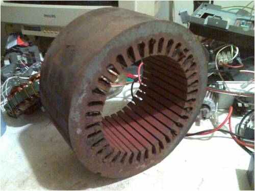
What I like about this stator is that there is nothing touching the outer periphery of the laminations and they are not welded together. The lams are clamped together and suspended in the air with no contact to anything along the depth of the stator. The only blemish is a small notch that I will use to align them back into a complete stator. I removed the case from the stator with a hacksaw blade...wish I had an angle grinder 
I am in the process of separating each lamination with a one ended razor blade...I only have about 70 more to go before I finish
A painful job time wise and patience is needed not to distort the laminations when separating them from each other. The next picture shows that I think I have resolved my main issue...finding a rotor to fit inside the stator. I have several old ceiling fans in the back shed and I toyed with the idea of fitting a square peg in a round hole... 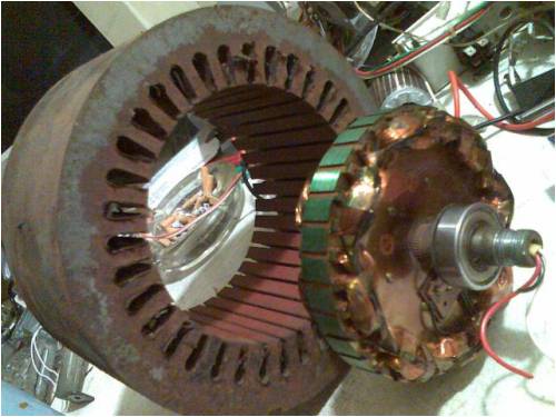
As luck would have it, as I was separating the laminations to be cleaned, I realised that I may be able to fit something inside the inner diameter of one of the rings...a rotor from a ceiling fan... 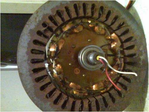
the air gap is 2mm between stator and rotor. I am not really happy with this large air gap, but it will have to do, as that is all I have got laying around. What I have noticed from playing around with my ceramic magnets, that if two alike poles (e.g. N/N) are sandwiched between a stack of laminations, magnetic "power" is increased to one end. So I think that the air gap should be okay with the "teeth" of the rotor enhancing magnetic magik towards the stator "teeth". I plan to use several more of these rotors with an alternate stacking of stator, rotor, stator rotor etcetera. I think 25 laminations from the stator will fit each rotor and once I have removed the copper wire from the rotor, I believe some nice magnets will fit in the slots. I am leaning towards plain neodymium magnets as i believe that heat will not be problem with the unit. Once I have raised some more rotors, I will then find a means of getting a shaft together to hold my multi-layered pancake assembly together. I might even use the shafts already attached...I have not got to that point yet. Cheers and have a good weekend http://cr4.globalspec.com/member?u=25757 http://www.instructables.com/member/OzzyRoo/ |
||||
| AMUN-RA Senior Member Joined: 10/03/2007 Location: AustraliaPosts: 144 |
CO your the third Iv'e found they're all around if you know where to look Mick cranbrook down the river a bit Every day the sun shines & gravity sucks= free energy. |
||||
| oztules Guru Joined: 26/07/2007 Location: AustraliaPosts: 1686 |
Well Craze, You certainly are giving it a shake. If magnet costs are a problem, you look like you could fit the ceiling fan laminates all onto a shaft, use some sliprings and a voltage regulator and wind a rotor to replace the magnets. You can then control the output. looks interesting......oztules Village idiot...or... just another hack out of his depth |
||||
| CraziestOzzy Senior Member Joined: 11/07/2008 Location: AustraliaPosts: 152 |
...kewl, I know who to ask for spare parts for my monster
...and I bet you guys are responsible for the lack of F & P in Town http://cr4.globalspec.com/member?u=25757 http://www.instructables.com/member/OzzyRoo/ |
||||
| CraziestOzzy Senior Member Joined: 11/07/2008 Location: AustraliaPosts: 152 |
Cheers....I am thinking of something like that (fit all the laminates onto the one shaft from the fans). Will have to rub my rabbit's foot a bit harder and hope lady luck can produce some old fans the same diameter on my next trip to the local dump. *UPDATE* I finished removing all the wire from the rotor of the ceiling fan. Those laminates are really soft and had to take care not to warp/bend them. I do suspect that I may have to remove the lams from the shaft, as during the manufacture of these, the lams were distorted and won't be so great at high RPM. I still do not know at this moment what is my final specs as far as output is concerned, but I am aiming towards a low RPM setup. Oh well. Below are two photos of the rotor and stator design I plan to use...the last one has a ruler at top left and you can see the scale of 1 inch. 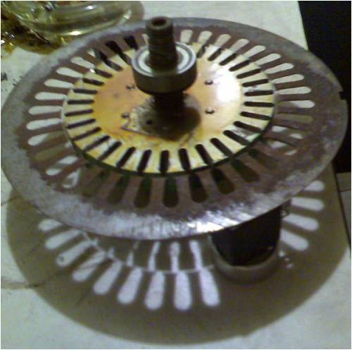
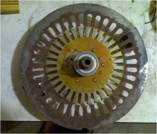
...how I am going to arrange poles on the stator is my next step, remembering that I plan to insert magnets ($$$)  into the rotor slots and wind the stator with wire. into the rotor slots and wind the stator with wire.
Not all the teeth on the rotor and stator line up opposite each other...I counted four that do with one at each 90 degree interval...I am still trying to figure out what this means. The adjacent teeth progressively become more separate until they realign again at the next 90 degree interval. I think the top view photo shows this. I hope some of you gurus might tell me what is great and not-so-great about the possibilities with the teeth alignment. Remember I plan to have each rotor tooth as a magnetic pole. Cheers http://cr4.globalspec.com/member?u=25757 http://www.instructables.com/member/OzzyRoo/ |
||||
| CraziestOzzy Senior Member Joined: 11/07/2008 Location: AustraliaPosts: 152 |
Just to clear up in my head what arrangement I think is best for the available rotor, I dismantled some hard drives and salvaged the magnets, broke them in half and slotted them into the rotor slots in the planned scheme sumwhere in the back of my head. I tested the magnetic strength with my high-tech measuring tool, a long metal bolt. I attached three bolts to the teeth of the rotor where the magnetic strength was strongest, which happened to be where two alike poles were sandwiched in between a rotor tooth. I had just inserted my precisely machined neo magnets... 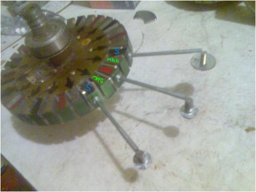
The black arrows show where I will place the larger magnets. I threw some heavier bolts on the ends of these long ones and was very happy with the depth and strength of magnetism. Ideal for reaching into the stator slots where I will have the copper wire. The tiny neo magnets although butchered and very unhappy, are amazingly strong and sniff out the laminations on the rotor like flies on sh*t ...can't wait to get some bigger ones and smash a few against my fingers.
next picture shows what I plan on doing to my rotor...I will somehow remove each tooth on the rotor (marked with a faint black square on photo) and insert snugly fitting neo magnets. The ends of the rotor teeth will mechanically hold them in place (with the help of some glue and a retaining ring either side of the rotor to stop them jumping sideways... 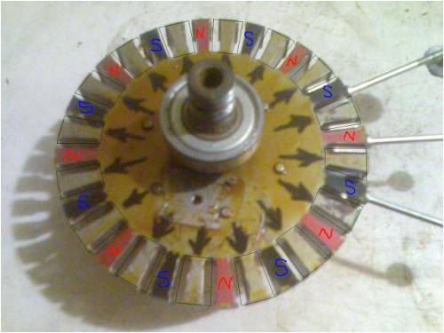
Once the magnets will be in place, the poles will be arranged like they are in the photo. I hope to try and figure out an ideal setup for a low RPM generator with a 36 slot stator. Any help and bullets will be very very very much appreciated....cheers again http://cr4.globalspec.com/member?u=25757 http://www.instructables.com/member/OzzyRoo/ |
||||
| AMUN-RA Senior Member Joined: 10/03/2007 Location: AustraliaPosts: 144 |
standing order at the dump near you not me but I know who.still plenty of f&p to go around I still have a grid inverter to give away to a good home for spare parts Mick. Every day the sun shines & gravity sucks= free energy. |
||||
| Page 1 of 4 |
|||||
| The Back Shed's forum code is written, and hosted, in Australia. | © JAQ Software 2026 |
