
|
|
Forum Index : Windmills : Peter would you Femm me?
| Page 1 of 2 |
|||||
| Author | Message | ||||
vawtman Senior Member Joined: 14/09/2006 Location: United StatesPosts: 146 |
I installed 1 mag on the wheel and just kept pacing around it 
My current thought is 54pole to reduce leakage flux but if you go by the book 66pl would be ideal. The ? i have would it be worthwhile to add the additional mags. I'll give you all the info you need and mail you a steak dinner and a six pack 
I can't figure out how to run it. Thanks |
||||
| Dinges Senior Member Joined: 04/01/2008 Location: AlbaniaPosts: 510 |
No problem Mark. As long as you give all the data to run a simulation. That means either a to-scale CAD drawing of your rotor, with magnets drawn on it too. Or full mechanical details of the dimensions of the rotor and magnets so I can make a CAD drawing. I prefer you make the CAD drawing yourself though if you can, preferably in .dxf format. If you don't, this is the data I'd need: magnets: - magnet size (LxWxH) (mm) - magnet grade (N35, N40,...) - number of magnets rotor: - rotor outer diamter (mm) - thickness of the 'backing steel' (mm) (i.e. rotor thickness) - number of spokes - width of spokes (mm) - diameter of hub (mm) - hole of hub (mm) - if it has some other fancy geometries that need to be taken into account... Can you upload a scanned drawing of the dimensions of your rotor and a picture ? |
||||
| vawtman Senior Member Joined: 14/09/2006 Location: United StatesPosts: 146 |
THANKS PETER 
I will have to go with the full mechaniical details option since i can't draw worth a crap. Magnets 1x2x1/2 N42 grade 54 or 66 ? Rotor 32in diameter 13 mm average thickness No. of spokes? Width of spokes? Hub hole is 1 5/8th Can you go by the pic i uploaded in my last posting or the Other ones The outer band(no mags) will be adjustable between 1/2 and 3/4 airgap and is 3/16 thick. |
||||
| GWatPE Senior Member Joined: 01/09/2006 Location: AustraliaPosts: 2127 |
Hi Dinges, It would be interesting to see a FEMM simulation from my axial flux design. I have twin rotors with two rings of 22, 25x25x12.5mm I think N30 Neo mags (first generation 1992 vintage) that are spaced with 0.5mm inner clearance between mags and about 4mm at the outside. The rotors are 10mm thick soft iron and are 27mm in width. The magnets are arranged, equally spaced around the rings. There is only 3mm airgap between the magnet rings, where the windings are placed. The windings occupy 2mm thickness so there is 0.5mm clearance on both sides between the rotors. I have noticed that when the rotors are separated that the magnetic fields are not contained by the iron rings. Some of the magnetic field breaks through the iron and returns through the air from the back side of the magnet. When the generator is assembled the fields become fully contained. I have only assumed that all the field lines form closed loops and are strengthened. I have aluminium backing plates that form the generator housing. I was surprised at the difference when the fields were closed. A FEMM simulator may be a waste of time, as the only iron has a fixed magnetic field in it and the air gap is so narrow compared to the magnet size. Your comments would be appreciated. Gordon. become more energy aware |
||||
| Dinges Senior Member Joined: 04/01/2008 Location: AlbaniaPosts: 510 |
Mark, see the results below. I simulated using N40 instead of N42 as there's no N42 available in the FEMM library. For comparison purposes between the 54 and 66 magnet variants it doesn't matter. The 54-magnet variant in close-up: 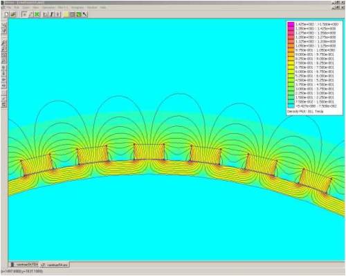
And for the 66 magnet variant: 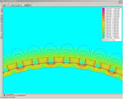
The high-resolution images can be found here: http://picasaweb.google.com/motorconversion/Temp (click on the magnifying glass to zoom in on the details) I made sure both scenarios have the same colour-legend so you can more easily compare the two. As expected, in the case of 66 magnets there's a bit more flux shorting. Also notice that in both scenarios the flux densities are rather small, in the 0.3-0.4 T range at the stator. This shouldn't come as a surprize for an aircore radial flux generator. Which is best ? Hard to say. In the 66 magnet variant there's definitely more flux shorting/leaking from magnet to magnet, without being useful in the stator. I'm curious as to other opinions in this matter, but it may just be that the extra 12 magnets may give not much better results because of this. Not sure how one could easily quantify this though. What I did so far is simply count flux lines and guesstimate that only 1/3 (and likely just 1/4 in the 66 magnet variant) are actually useful (at one magnet-thickness away from the magnets). Of course, much also depends on how thick you will make your stator. I think the above results show that the thinner your stator is, the better the results. |
||||
| Dinges Senior Member Joined: 04/01/2008 Location: AlbaniaPosts: 510 |
Gordon, I don't mind helping out but I'd rather people learn to use the software themselves, it isn't so hard to do. 'Teaching a man to fish', as opposed to giving him a fish. Vawtman is the exception of course, it's a personal victory for him to get his digital camera working without the help of his daughter 
From your description of the generator I can not visualize how it exactly looks/works. I have always needed pictures to visualize this kind of thing, somehow I just don't 'get' it from reading a block of text. Can you make a to-scale CAD drawing (.dxf) of it, or else a good hand-drawn sketch that also shows the critical dimensions ? That'd give something to start from so we could take it from there. |
||||
oztules Guru Joined: 26/07/2007 Location: AustraliaPosts: 1686 |
It looks wrong dinges. We seem to be missing the outer band :Vawtman says "The outer band(no mags) will be adjustable between 1/2 and 3/4 airgap and is 3/16 thick. " I read this as being another metal band. I seem to recall that he was using wire or similar for a flux intensifier. Of course he may have meant something else. .........oztules Village idiot...or... just another hack out of his depth |
||||
| Dinges Senior Member Joined: 04/01/2008 Location: AlbaniaPosts: 510 |
Ah. I didn't understand that part of his comment. Should've checked with him what he meant. I recalled that about a year ago on FL he published his experiments with a rotor that looked like the one I had drawn above and made a testmagnets and a teststator out of particleboard. But apparently the plans have changed since then. So he'll attach an outer ring to the rotor ? I'll wait running another simulation till Mark can confirm exactly what the plan is but I think you're right, Oztules. An adjustable outer band... Mark, can you specify for what distance you want it simulated (1/2", 3/4" or in-between). Just specify a distance, not a range, please, as each simulation run takes about an hour calculating (plus an hour to draw/model), so two scenarios (54 & 66 magnets) is doable, but 4 or more is going to take too much time. The above is the exact reason I keep going on about needing good, detailed sketches and needing full details. Blocks of text just don't convey the same information. And this accidently confirms what I wrote to Gordon... Pictures and 1000 words and stuff... |
||||
| GWatPE Senior Member Joined: 01/09/2006 Location: AustraliaPosts: 2127 |
Hi dinges, I though you were familiar with dual rotor axial fux machines. My generator is basially a dual rotor machine with 22 magnets per rotor with a 3mm air gap between the rotors. The magnets are not true segmented shape. There is a segmentation gap between each magnet of 0.5mm on the inner edge and 4mm at the outer edge. I am trying to get some time to gather data on comprisons on different configs of F&P stators with and without capacitors and maximiser. I have just downloaded the FEMM software. I may explore it in the future. As I said above, there may be no useful purpose to simulate my design. I will be pubishing photos on this site when my F&P machine is up and running. Gordon. become more energy aware |
||||
| vawtman Senior Member Joined: 14/09/2006 Location: United StatesPosts: 146 |
Hi Peter Yes what oz said is correct. The outer ring will be attached to the rotor and is 5mm thick.Let's use 12mm for the gap.Magnet face to band.I'll put something together and upload a pic later. Remember also that there are no mags on the band. Thanks again Peter |
||||
| Dinges Senior Member Joined: 04/01/2008 Location: AlbaniaPosts: 510 |
I'm a little familiar with them. Just that your dimensions (3mm airgap; .5-4 mm between magnets) and number of magnets (22; so not a 3-phase genny then ?) were so far out of the range of what I consider to be a 'atandard' axial flux that there was enough doubt in my mind as to whether it really was an axial flux or something else. Then there's the bit where you say that the rotor width is 27 mm... As I said, different from the axial fluxes I'm familiar with it. As to simulating with FEMM... I think it'd be hard. FEMM is a 2D package. It can't account for the varying distance (.5-4mm) between magnets, you'd have to pick one particular value and simulate for that, or run multiple simulations for different distances. About the 3mm airgap and .5-4mm distance. Very small. I did in the past run some other simulations to determine airgap flux in a more standard axial flux generator, where the magnets sit at a distance equal to one magnet width whilst varying the airgap. The results (though not immediately applicable to your genny) may interest you too: http://www.anotherpower.com/gallery/album89 |
||||
| GWatPE Senior Member Joined: 01/09/2006 Location: AustraliaPosts: 2127 |
Hi dinges, If you imagine a circular ring of iron with outer dia 233mm, approx 27mm between the inner edge and the outer, with 22, 25.4mm square, 12.5mm thick, polarised between the square surfaces, and the magnets arranged around this ring, with 0.5mm gap between the inner corners of the magnets, then this is one of 2 rotors. The rings are bolted to aluminium discs that form part of a closed housing. There is still 3mm airgap between the magnet surfaces. The gap is constant. This is a standard dual rotor axial flux arrangement. The electromechanical windings are of 4 phase, with 11 series coils per phase, with interwoven coil arrangement. The wiring is drawn out through the hollow shaft. The design was intended to carry the weight of a vehicle as a wheel motor in a solar car, hence the fully closed housing. I have previosly posted a photo of a failed 3phase test stator on this site and otherpower. Many people have queried the narrow airgap. I can assure you that some readers have personally viewed a stator. I reiterate that I will be asking Gizmo to add some photos of my setup to the relevant pages on this site, at a time when I get to dismantle my systems and photograph and then collate with a suitable dialogue. I rely on my mill to provide power to my home, so I am unable to fully dismantle until my second mill is operational. As a matter of interest, what magnetic field strength would you expect between a pair of N50 1"x1"x0.5" Neo blocks at a spacing of 1/8". This would be approximately 1/44 of the total field. In my design the field from both ends of the magnet is combined to pass back through the adjacent magnets, as in a dual rotor design. I designed my generator quite a while ago now. I had the idea to have the strongest magnetic field with the lowest possible wire resistance with the lowest possible eddy current losses. I did not rely on simulators. All of my research was based on iterative testing of wire types, coil shapes and magnet spacing. I also had to be able to build the device without outsourcing or welding. I did have a mill, lathe, drill press and hand tools though. This was at a time when a PC was a luxury item. This is probably academic, as I am not in a position to replicate my design. My testing did sway me towards a narrow air gap. I think that mechanical limits dictate a more modest air gap as in typical air cored designs as presented by otherpower and others. I do agree that I had a lot of difficulty with wire sourcing and coil winding and moulding. The magnets were rare and expensive. The machining tollerances presented other problems. This is getting off topic, so I will get back to my maximiser. Gordon. become more energy aware |
||||
| Dinges Senior Member Joined: 04/01/2008 Location: AlbaniaPosts: 510 |
Gordon, Thanks for the explanation. It's now beginning to make sense. If you built that generator back in '92 then you were definitely on the cutting edge back then. No wonder that some parameters differ from what is now considered 'normal' for an axial flux. As far as the narrow airgap goes, I've had some discussions with Wdyasq (RonB) on IRC about this, where he had the idea of using an extremely small airgap and thin stator, possibly made of copperclad and etched PCB. Would be interesting to see how the higher flux density compensates for the much diminished room for stator coils, and whether it performs better or worse than the standard design. Genny design isn't an exact science, a lot of trial and error is involved and over time a certain design has evolved as 'optimal'. Only time and more trial and error can tell whether the 'normal' axial flux is really optimal, or sub-optimal (with e.g. your variant being better). I, for one, would definitely be interested in seeing some pictures when you get it down for maintenance, and the story that goes along with it. As far as the N50 flux density goes, I can't simulate for that in FEMM as the highest grade magnet in the library is N40. It should be possible to add new magnet variants to it though, have never done it myself yet. Another option would be to use the curve for N40 magnets ( http://www.anotherpower.com/gallery/album89/axial_flux_airga p_sim_graph) as the basis for a little extrapolation... N40 with an airgap of one magnet thickness (12.5mm) gives a flux density of 0.75 T. Now, if we look here: http://www.kjmagnetics.com/surfacefield.asp and compare the products 2"x1"x.5" both in N42 and N52 grade, we see that surface field flux density is 6325 Gauss for N52 and 5910 Gauss for N42. The N52 is about 7% stronger at the surface level. So, if we extrapolate the flux density from the graph with 7%, we get 0.75T * 1.07 = 0.80T flux density in the airgap (N52, 1/2" airgap). The fact that my original simulations and graphs were for 2"x1".5" magnets and not your 1"x1"x.5" ones is irrelevant, as FEMM is a 2D package that 'doesn't see' the 2" dimension (into the screen). That's the best I can do at the moment, short of simulating. Will take a bit of effort to try and incorporate the N50 material in the FEMM library, not sure if I'll manage to get it done anytime soon. |
||||
| vawtman Senior Member Joined: 14/09/2006 Location: United StatesPosts: 146 |
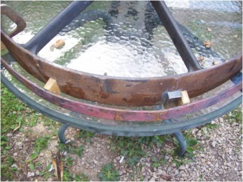
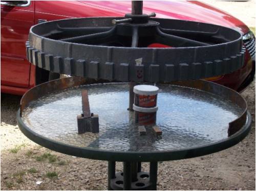
This pic isn't pretty  But will get prettier has time goes on But will get prettier has time goes on
Should give the basic idea though.The infamous plywood mags are just used has spacers now  |
||||
| vawtman Senior Member Joined: 14/09/2006 Location: United StatesPosts: 146 |
To Gordon Someday i may be able to help you with uploading pics
Starting to get it 
P.s maybe you could even start your own post. |
||||
| GWatPE Senior Member Joined: 01/09/2006 Location: AustraliaPosts: 2127 |
Hi Dinges, Thanks for that explanation. I do not follow the 37 of 37 picture from the above link of a dual rotor with dual airgaps. I assume this simulation is for a dual rotor with iron core in the stator. ???? I can see why the waveform I see in my machine is so much different to the designs with larger airgaps. In my machine the coils move in an out of a constant strength reversing magnetic field. The pictures you refer to in the link show the magnetic field disperses as the airgap increases. This would result in a more sinisoidal output waveform. This would only be an advantage if a transformer coupling to a load was employed. My understanding is that in an air cored machine that as the electromotive opposing force increases, that the flux lines would tend to move in space around the coils in the airgap. The flux density may be higher with a 3mm airgap. There would be less flux leakage. The arrangement I have with a dual rotor and the fields guided back through adjacent magnets could further strengthen the fields. This would account for the 0.2V/turn @ 300rpm that is output when fully load. I do measure high efficiencies. The output behavior is similar to an iron cored machine with 0.2mm airgap without the iron hysterysis losses or cogging or weight. The square wave output waveform is a bonus for rectification, and output filtering. I may look at replacing the magnets in my machine with modern higher power types. The cost would only be hundreds and not thousands of dollars. The only problem I can see is assembly. The current arrangement is already at the limit of hand tools for disassembly. cheers, Gordon. become more energy aware |
||||
| Dinges Senior Member Joined: 04/01/2008 Location: AlbaniaPosts: 510 |
Mark, Here are the corrected simulations, sorry for the delay. 54 magnets: 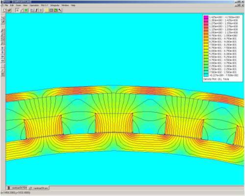
66 magnets: 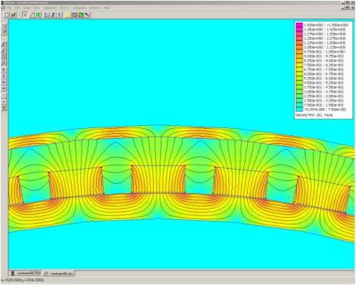
The high-resolution images can be found here: http://picasaweb.google.com/motorconversion/Temp As you can see, there's slighty more flux shorting in the 66-magnet variant, but the difference is much less than without the steel outer ring, as was to be expected. One more thing about the generator: will you be trueing the outside circumference of that wheel, on a lathe or something else ? Wouldn't be easy to do but the slightest wobble or non-roundness can have a dramatic effect on the extra clearance you will need to prevent the rotor rubbing the stator. With the large 'arm' (diameter) of that wheel, the slightest error that has been made in the machining of the hole in the hub will have a profound effect on wobble. This may not affect its function as (slow-turning) wheel much, but could be an issue for your genny. |
||||
| vawtman Senior Member Joined: 14/09/2006 Location: United StatesPosts: 146 |
Your the greatest and can't thank enough.
On the last simulations the lines flatten on the outer edges of the steel.Would that simulate slight losses there?No big deal though i would think. I've spun it to the upper range of the turbine(180rpms)and looks good.Spent alot of time building the shaft. Would you be interested in X20 reverse direction speed increaser for payment instead?I have many thoughts for it but i have 2.I will upload a pic of it if your interested.FREE for you Mail me your shipping addy.I know your out in the boonies but thats o.k I think i'll leave it at 54 based on the femm. Mark |
||||
| Dinges Senior Member Joined: 04/01/2008 Location: AlbaniaPosts: 510 |
No worries Mark, was my pleasure, no need for payment. Though I *was* kind of looking forward to that steak dinner... About those speed increasers... have you considered putting them in series ? By a mere flick of the input shaft you'd end up with 400 times the RPM... Should prove ideal for matching a *very* slow VAWT to a generator...
(just kidding; in my mind I already see Ron cringe as he reads the above) Looking forward to reading more about progress on your contraption. |
||||
| vawtman Senior Member Joined: 14/09/2006 Location: United StatesPosts: 146 |
Mags are on  Now to start on the outer band.Part of it is on the table. Now to start on the outer band.Part of it is on the table. |
||||
| Page 1 of 2 |
|||||
| The Back Shed's forum code is written, and hosted, in Australia. | © JAQ Software 2026 |
