
|
|
Forum Index : Windmills : my Lenz2 attempt
| Page 1 of 3 |
|||||
| Author | Message | ||||
gj4533 Newbie Joined: 28/12/2008 Location: United StatesPosts: 19 |
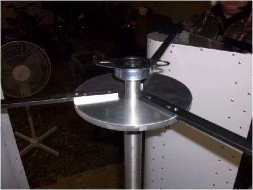
I decided to try and make a Lenz2 without using wood. The end and center pieces are polycarbonate. The braces are made of aluminum trim bent to form a channel. The wrap is also aluminum trim and it's held together with #6 sheet metal screws (1/8 pre-drilled into the poly) and about 100 rivets. Each wing weighs just under 4 pounds. Being a machinist I have access to metal and machines so I made the top and bottom hubs out of aluminum, and the arms to tie it together is 1/4" X 3/4" flat stock. 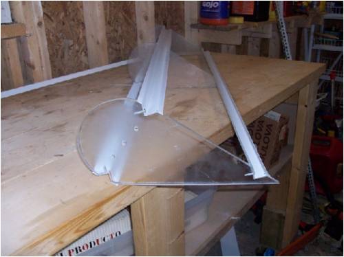
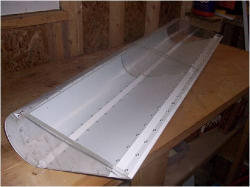
I connected an ac servo motor from a cnc lathe x axis. The blades were driven from a 19" house fan and the rpm was 34. 4.2 volts rectified. I dragged it outside into some wind. I have no idea what the wind mph was but at one point it generated 34.4 volts and was completely stable. The ratio was not quite 2 to 1 at that time. I have since changed the ratio and now I'm getting 8.4 volts inside with the fan blowing it. There is alot of torque and my thoughts are now turning to making my own stator but my questions are regarding just that. Most online stators are 8to 10 inches and made for machines with more rpm. Could I get the same thing from making a 12" to 14" stator? It has more torque. Every inch in diameter adds 3.14" to the circumference so 2 inches bigger would would have over 6" of movement across the coils. The overall of the machine is 3'(dia) 4' tall. I've had it in pretty good wind (30+ gusts) and it held together and ran very smoothly, although at that time I didn't have the generator connected. All and any input is greatly appreciated. G.Johnston |
||||
| Gizmo Admin Group Joined: 05/06/2004 Location: AustraliaPosts: 5182 |
Hi gj4533 Thats a neat looking job. I cant offer much advise on the best axial flux alternator to build, maybe Ed could help with that. Could you use the Servo motor on a permanent basis? Glenn The best time to plant a tree was twenty years ago, the second best time is right now. JAQ |
||||
| Jarbar Senior Member Joined: 03/02/2008 Location: AustraliaPosts: 225 |
Hello Garry and Glenn,I think I have asked a similar question in the past but something was lost in the translation.Great work with your VAWT development by the way Gary. If the standard F&P or any other similar device has 42 poles and 2 has 84 and 3 has 126 why is it not possible to rewire them to give the effect of a larger diameter stator.Having many more magnetic pulses occurring at lower rotational speeds.Something that I imagine would benefit VAWT's.Instead of gearing up the generator.So if you were to stack 2 stators and offset equidistant between poles how would the wiring change to achieve this outcome.ie double the poles and halve the revs.I know my electrical inadequecy is showing so don't be too hard.I tried to have this answered by Eco-Innovation and their rewire manual but to no avail.I see Vawtman is building a large diameter stator/generator,I suppose I'm trying achieve this electrically.Does the electricity know if poles are stacked or all in a row??? Hope this makes sense. Anthony "Creativity is detirmined by the way you hold your tounge".My Father "Your generation will have to correct the problems made by mine".My Grandfather. |
||||
| gj4533 Newbie Joined: 28/12/2008 Location: United StatesPosts: 19 |
Thanks for the compliments and advise. Glenn, I hooked up the servo and was convinced I was going to use it on a pemanent basis, until I decided to make another one to mount on the other side of the pole that will hold this one. I want both mills to be exactly the same and I can't get my hands on another one of the servo motors (unless I can convince the operator of the cnc lathe to rip the gearbox off another machine for me). The power loss is pretty substantial using a v-belt. It didn't even want to turn until I cut alot of slots from the id towards the od to make it alot more flimsy. I tried a sprocket and chain from a 15 speed bike but that didn't last that long. I only have hand tools here at my land and did the best I could but it didn't run true enough to keep the chain at an even tension and it just fell off. Anthony,I'm not sure if I can get an F&P but there is alot of people talking about them, and thinking about them kept me up last night. At work today I put my thoughts into a drawing to see if it was feesible to make. 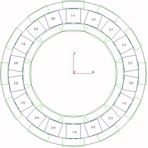
The magnets are on both sides of the coils. The od 1s 10". The magnets are 1.5". My concerns again are the coils. They are 1" in diameter and 1" long 72 turns of 18gage wire. That means the diameter of the inside of the magnets are only 3/8". Is this a bad thing? Should I fill it with something or leave it open to air? I need to have an electrical engineer on my payroll. Here's the housing drawing. 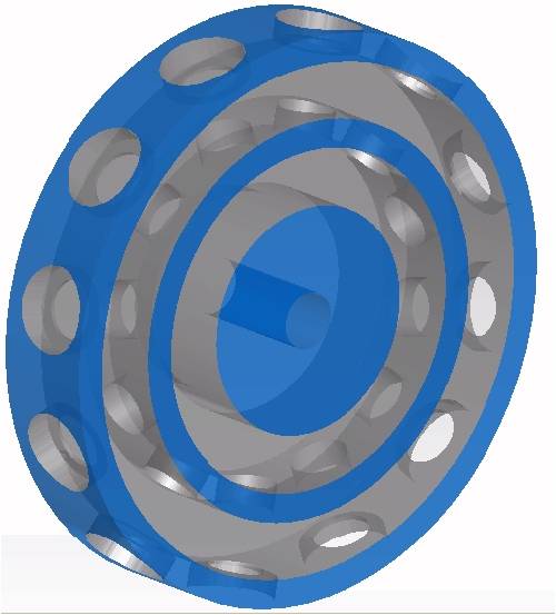
Thanks again for the help and compliments. Gary G.Johnston |
||||
| Jarbar Senior Member Joined: 03/02/2008 Location: AustraliaPosts: 225 |
Gary these links may be of interest.Great rendering.Vawtman in these links is travelling a similar path I think.And one I may need to pursue ultimately with the alternator. http://www.thebackshed.com/windmill/forum1/forum_posts.asp?T ID=1218&KW=vawtman&PN=0&TPN=2 http://www.vawts.net/index.spark?forumID=125317&p=3&topicID= 21439905 http://www.vawts.net/index.spark?forumID=125317&p=3&topicID= 21352540 P.S I tried these links but none turned up to the correct page????? Sorry for the confusion.Go to Search list for Vawtman then Subject, Peter can you FEMM me. P.P.S There are some very clever people in this forum,I struggle to hold their coat tails.But they are very forgiving and educational. Anthony "Creativity is detirmined by the way you hold your tounge".My Father "Your generation will have to correct the problems made by mine".My Grandfather. |
||||
Gill Senior Member Joined: 11/11/2006 Location: AustraliaPosts: 669 |
For some reason web addresses always appear with an added space in the address that should not be there. Simply copy and paste then edit out the space and you're set. .asp?T ID=1218 ........^ here 3&topicID= 21439905 ..............^ here 3&topicID= 21352540 ..............^ and here was working fine... til the smoke got out. Cheers Gill _Cairns, FNQ |
||||
| Dinges Senior Member Joined: 04/01/2008 Location: AlbaniaPosts: 510 |
What material will you be making the rotor from? Keep in mind that it can not be steel (or any other ferro-magnetic material) as it will short the flux of the magnets. Also, for effective use of the available magnetic material, there should be steel behind the magnets to conduct the flux from magnet to magnet. If you have a look at the links above you'll see that's what Vawtman is doing too. For another illustration have a look at some of the motor conversion rotors in the images below. Notice that the bottom of the magnets must be on a steel surface but that the magnets themselves must not be (completely) embedded in steel, as otherwise the flux will be shorted. Hence the aluminium sleeves you see in the pictures below. 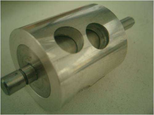
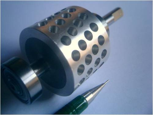
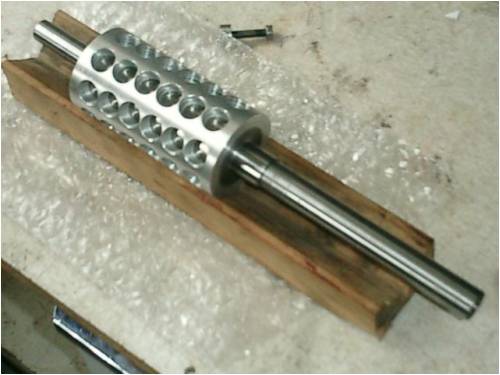
For effective use of your magnets, you need a steel inner core for the inner ring of magnets, and an outer ring of steel over the outside of the rotor to conduct the flux of the outer ring of magnets. Peter. |
||||
| GWatPE Senior Member Joined: 01/09/2006 Location: AustraliaPosts: 2127 |
Hi gj4533, You should look up a motor designed by UNIQ mobility. This was similar to what you have shown. These had very high power density. They needed forced air cooling though. I saw quite a few used in solar racing cars in 1990,1993 WSC. Gordon. become more energy aware |
||||
oztules Guru Joined: 26/07/2007 Location: AustraliaPosts: 1686 |
Gary, there are a few things that are worth knowing when designing your alternator. To make best use of your magnets (which you need to do to get good results at low rpm), it helps to keep these things in mind. 1. If your magnets are 1.5" by X inches, then the most useful practical distance from the magnet faces opposing each other is about 3/4 to 7/8 of 2 times X. ie if your magnets are 1/2" thick then about 3/4 to 7/8" gap is about ideal. (winding space is just as critical as flux) 2. If your magnets are 1.5" diameter, the inner diameter of your coils needs to be no less than about 4/5 of the magnet diameter in practice. (Theory says the same size, but in the real world, the inner turns although less efficient than the 1.5" diam, cost less copper per turn,and so less resistance for reasonable gains. After this, it gets less useful going smaller)... so for 1.5" diam magnets, then 1.2" is about the smallest inner diameter to go down to. 3. You should endeavour to complete the magnet circuits as Dinges has pointed out. This means giving the flux lines an easy path to follow from the front of the magnet to the back.... but going through your air gap.... so 1/4" minimum backing behind the magnets of steel. ideally more, and if your using 14" disks, probably 5/16 will be better mechanically. This will give the back N pole of one magnet an easy path directly to the S pole of the magnet next to it. The front poles will have to travel through the air gap, but the opposing magnet will "draw" the lines from the face of the magnet opposite it to itself... and then back through it's backing plate to the magnet next to it's back on so it goes. 4. Use as bigger diameter of plate as you can get away with. As you pointed out in your first post. 14" would be an excellent choice.... although way too big for the power you may expect.... but the vawt may grow. 5. The Vawt suffers from an expensive use of materials to get swept area, so all power developed is precious. In view of this, use no gearing, use no steel in the stator, and as good a magnets as you can afford. 6. If you use round magnets, then round coils are perfectly fine. In my testing, they seem to be ideal. 7. An axial is very much easier to build than a radial unit, as the tolerances are easy to adjust. Also, there seems to be less crowding of the coils and particularly the magnets on the inner ring. Try and keep the magnets at least 1/2 a magnet width apart to minimise inter magnet leakage(flux going from one magnet to another sideways from the front poles... you want all of the flux lines going across the gap through the coils) and to give you enough winding space. 8. After all of that, build your rotors and mount them.... and then wind a test coil... and test the turns per volt. Then and only then can you decide how many turns you need to wind for cut in that is appropriate for your turbine. 9. When you know the turns you require, then wind your coils to fill the available space with as bigger wire as you can stuff in it whilst remembering, you will need 2mm or so on each side of the stator for mechanical clearance... so if we had say 1/2"thick magnets, we would want to keep the stator thickness to around the 1/2"-5/8" thick max mark. For the modest amount of power you would expect from this machine, this is all over the top. 14" disks with proper design will be a powerful alternator... which is far and away too much for this project, but it should give you an idea of what you need to do to design a good alternator. Axial flux is the best alt for the least losses, and is the easiest to build. The radial is a bit more demanding of design, and clearances etc. If you have difficulty picturing the magnetic flux business, Dinges has done some terrific femm plots to give you the idea here: Just my thought on it .........oztules Village idiot...or... just another hack out of his depth |
||||
| oztules Guru Joined: 26/07/2007 Location: AustraliaPosts: 1686 |
The electricity doesn't know or care if they are stacked or in a row.... so long as the sequencing is correct. If you stacked two F&P stators, and kept then in an identical alignment (no offsetting), you could series the windings of both stacks and get double the voltage at the same rpm, or the same voltage at 1/2 the rpm... but the cogging would also be double in this instance. The number of poles is immaterial. It is a function of how small your magnets are, and how big the diameter is that will dictate pole count.... then it is how many turns of wire you can squeeze in that will effect your voltage, and whether you series them or do as Jerry does and rectify them all independently, or wire them star or delta etc. .........oztules Village idiot...or... just another hack out of his depth |
||||
vawtman Senior Member Joined: 14/09/2006 Location: United StatesPosts: 146 |
Happy New Year everyone 
Hi Gary Nice lookin turbine your building there 
Peter and Oz pretty much filled you in with the basics 
I also struggled with gearing early on and decided there had to be a better way.One day when visiting my mother in law i spotted this wheel sitting up against the house.Hmmm brain cells started arcing again 
I think the 1x2x.5 mags are ideal for radial machines.You can get them cheap and they sit nice on the rotor.One other advantage of the radial is more efficient windings can be done.More coils and mags with fewer turns of thicker wire. On mine the outer band has no mags just steel for the return path and spins with the main rotor to neglect the losses associated with neo's spinnin against stationary steel. On your vawt you could use say a 12in pulley(+36in cir.)Say maybe 24pl.or more.Doubling the speed of the standard 12/9. Have fun Mark |
||||
| vawtman Senior Member Joined: 14/09/2006 Location: United StatesPosts: 146 |
Oops i meant Hertz(cycles) not speed. http://www.fieldlines.com/comments/2008/12/30/31858/420/4#4 A recent comment by Flux at Otherpower. Gizmo it doesn't appear to be an active link?Did i do something wrong here  |
||||
| oztules Guru Joined: 26/07/2007 Location: AustraliaPosts: 1686 |
Vawtman. Use the fourth button from the left (world one next to U). answer the question of screen display (such as link to flux etc). Then the next box comes up, paste the url there, and it will end up like this: vawtmans link to flux It's not like fieldlines where the program generates active links whenever it sees a url, you have to deliberatly make it active. Also, beware of misinterperating Flux's comments here. They are comparative of two scenarios. increasing pole count, just to get increased frequency.... without using a larger diameter, will improve little. The magnets will be smaller to squeeze them on, or they will be so close together that leakage will become a problem, and winding space will become premium realestate. Using the same material as two identical units, it is much better to use all the mags and wire on a larger disk,(which will give you twice the pole count at the same spacing as the smaller disk) than the same bunch of materials on two identical units stacked together. With larger disks come all sorts of goodies, higher periferal speeds, so less turns per volt... thicker wire for the same space, better cooling.... better everything. Pole count should be determined by circumference allowing the magnets to be somewhere between 1/2 and 1 magnet space apart. Happy new year Vawtman... is it snowin there? ........oztules Village idiot...or... just another hack out of his depth |
||||
| vawtman Senior Member Joined: 14/09/2006 Location: United StatesPosts: 146 |
Hi Oz When i asked Peter for Femm help leakage flux was my main concern.It seemed to show with fewer mags the alt would be more efficient overall and not worth the addition of 12 more poles.If mags were installed on the outer band then leakage wouldn't be much of a worry but double cost and scarry building.Not to mention expensive for little gain.(just me) Lets say one has a 12in 12pl dual axial(dual mags)9cl and one has 24pl(36in cir)so roughly half the mag width(not bad mines a hair over that)He could run 72 low turn coils over 9 for the stock axial..Same amount of mags only on one rotor. Remember we're talking a vawt with a tsr<1 Snowwise one of the rare days with no snow here.BAD records broken(thanks al gore)That storage bin you offered is lookin better everyday. I set up shop in the basement 
Happy New Year Oz |
||||
| gj4533 Newbie Joined: 28/12/2008 Location: United StatesPosts: 19 |
Wow, a bit overwhelming response. First I'd like to wish everyone a happy new year and thank all of you for being here and sharing thoughts and experiences. It's people like you (and me too a little) that change worlds and solve problems ... Kudos. I'm not sure who asked what But I think Peter asked me what I was making the Rotor out of. Today at work I had the saw man cut me a piece of Aluminum (alu-minium for you across the pond)10"X2 5/8".I need a flange on one side down to about 3" x 3/8" deep for set screws to attatch it to the shaft. Axial magnets are right directly next to each other, is there loss of flux because of that? If the coils are 1" in diameter do I need 1 1/2" magnets? Is there an advantage to the bigger magnets? The outside lip of the design is 1/2". Do I need to put a steel ring all the way around the outside, or can I use backers behind each magnet. The way you described it the steel connects the magnets together, so a ring is the way to go? What is the diameter of the P&G everyone is using? Anyway, The groove is an inch wide and I can make it up to 1 3/4" deep into the face. If my coils are 1" dia. They shouldn't be 1" long? I haven't purchased the magnets yet, the wire is on order but now I won't be needing that much because I shouldn't make the ID of the coils that small? I'm not sure if I made it clear that the magnets are on both sides of the coils I'll need another steel ring on the iside as well? Or backers? Is there a difference in the steel used? High levels of iron or not? There must be. I'm rambling, my head is spinning and I won't be sleeping again tonight. Oh one more thing, because of the difference in circumference of the magent rings, I thought maybe cogging wouldn't be an issue because the inside magnet ring would start having an effect on the coil before the outside one gets there kinda easing the shock, I wonder if the wave form would be different from a "normal" cycle, maybe stretched out a bit. my brain hurts. Gary G.Johnston |
||||
| gj4533 Newbie Joined: 28/12/2008 Location: United StatesPosts: 19 |
After all the information given (thanks to Oz), I have decided to re-vamp the design a bit. Please let me know if I'm on the right track. I've decided on 3/4 X 3/4 magnets. The coils will be just under 1" long and just over 1" in diameter with a 5/8" id. There will be metal rings around the outside of the mags to connect the flux and keep them from flying away. There will also be a ring inside to do the same at the other end of the magnetic field. Is this design abit better? 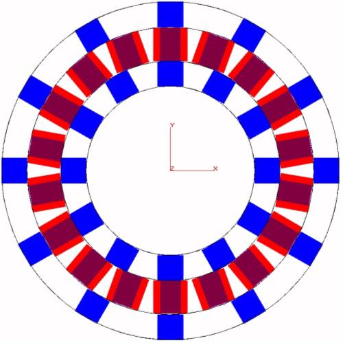
In order to re-vamp we must first vamp. Gary G.Johnston |
||||
| GWatPE Senior Member Joined: 01/09/2006 Location: AustraliaPosts: 2127 |
Hi Gary, I suspect that this will produce a strange output waveform. This will be a very peaky waveform. This will produce high peak voltages unloaded, with a lower average than a sine wave. Any gains with the small coils will be lost with the magnetic fields. This arrangement would only become useful when the magnet dia is approx 1/20 rotor dia. Gordon. become more energy aware |
||||
| oztules Guru Joined: 26/07/2007 Location: AustraliaPosts: 1686 |
"Is this design abit better"...... yes, but it is not ideal. A low speed alt will benefit from large magnet surface area, least dead space in the rotation plane, as well as all the other things I mentioned previously. In this case, as Gordon pointed out, it will be peaky, and you have a lot of space there with no wire. The magnet area is very small, and although you have solved the leakage problem, you have too much unused space. I expect it will work fairly well, but for the effort involved, I think you will do much better to not re-invent the wheel and follow Ed's design. You have a beautiful lenz turbine, and Ed has matched it to the best alt he could. (and he has built many and all kinds)... So the best advise I can give is to follow Ed on this one with this combination: 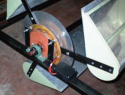
It may not be as sexy as an aluminium radial, but it will give the best results for this unit. The radial will work nicely, but I think the resistance will be greater than Ed's axial. With alts, it is all about resistance in the windings, and how to get it to a minimum for the volts you want out at the revs you are stuck with..... one big balancing act...... So the best advice is to re-read this ed project again and then decide what to build. Remember, there is no furling with this style of machine, so you need an efficient alternator to stop it running away in big winds.. ...........oztules Village idiot...or... just another hack out of his depth |
||||
| vawtman Senior Member Joined: 14/09/2006 Location: United StatesPosts: 146 |
Thanks Oz I was trying to link him to Eds sight.(world one next to U).No clue. |
||||
| gj4533 Newbie Joined: 28/12/2008 Location: United StatesPosts: 19 |
OK Oz and Vawtman, I'll make it like Ed's. I got sidetracked with everyone talking about P&Gs or whatever and I thought that would be the way to go. I wasn't insinuating that Ed's design was not good, I never questioned that. What I was thinking was his stator was designed for a hawt that turns alot faster so my original idea was to make it bigger in diameter so the speed of the magnets acroos the coils would be faster at a lower rpm. Then I got sidetracked with the washing machine moter. Thanks for the input. Gary G.Johnston |
||||
| Page 1 of 3 |
|||||
| The Back Shed's forum code is written, and hosted, in Australia. | © JAQ Software 2026 |
