
|
|
Forum Index : Windmills : 2HP Motor Conversion
| Page 1 of 2 |
|||||
| Author | Message | ||||
Bryan1 Guru Joined: 22/02/2006 Location: AustraliaPosts: 2102 |
Hiya Guy,s Well after dinges prompting I've decided to start on this conversion. I've machined the new rotor to spec's 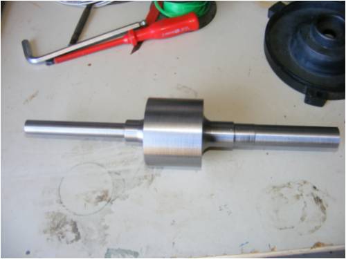
Now to get the 43.75 degree angle today I spent 4 hours just to find out my division plates on my dividing head wont do the right angle. To get the right angle I need to make a 105 hole division plate and use 96 holes and 4 turns. This is what took 4 hours to work out. Cheers Bryan  |
||||
oztules Guru Joined: 26/07/2007 Location: AustraliaPosts: 1686 |
Bryan, I don't use your style of index head, mine is a rotary table that I would use to make the appropriate angular locations to mill from. Rather than trying to dial up 43.75 degrees each time, perhaps just use the 360 degree graduations on the perimeter (I assume it must have for reference sake) and use these calculated positions as a reference: "43.75, 87.5, 131.25, 175, 218.75, 262.5, 306, 349.75" That way, if you get creepage, you will know straight away, other wise you may get a gradual error that will make this style of decogging not work too well. Hope that helps a bit to keep the errors small/tiny. Dinges may be able to help get a better idea on the right indexing plates. ..........oztules Village idiot...or... just another hack out of his depth |
||||
| Dinges Senior Member Joined: 04/01/2008 Location: AlbaniaPosts: 510 |
Good to see work on the conversion is progressing. The rotor looks very nice. I'm not sure what the problem is with the dividing head, I've never had problems with the fractional angles in my projects and frankly, *any* dividing head worthy of that name should be able to accomplish this .25 deg angle. But you are likely more familiar with your dividing head than I am. If it's anything like this one it should be a piece of cake. 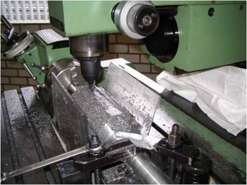
I'm not sure what angles your dividing head *can* do. If it'd do 43.74 or 43.76 I expect it to be fine too. I'd be very surprized if the only solution to get the quarter-degree angles would be by making new division plates. Don't you have a plate where each hole represents (a fraction of) 0.25 deg? Then simply start counting holes and revolutions as you swing the handle. Or do as Oztules say, rotate the head to 43 degree using the outer graduations. Then, add an extra 0.25 degree by counting the holes in the dividing plate (if there are 20 holes in the plate, put the lever in holes 0, 5 (.25deg), 10 (.50deg) and 15 (.75deg) respectively, after rotating to the proper integer angles (43, 87, etc. deg) first. Look on the bright side... if you had gone with the helix method, you would have needed to mill ~100 holes with two different incremental angles. Trust me, I have done this using a dividing head (see image below), it took a lot of time and effort. By using the offset-method you only have to set 8 angles in the dividing head. So if you think machining it this way is a nightmare, consider the alternative: 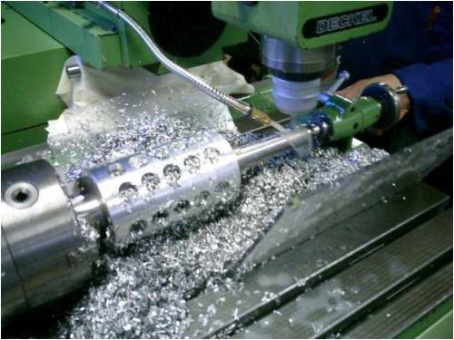
Incidentally, now you also know why I'll never use the helix method again for conversions. Not because it doesn't work, but because there are other, simpler methods that require less effort. Hence my advice to you to use the offset method and not the helix method (and also because you can cram much more magnet in the same space that way). Peter. |
||||
| Dinges Senior Member Joined: 04/01/2008 Location: AlbaniaPosts: 510 |
Bryan, After you mentioned you were going to cast the rotor in epoxy too I realized that, in that case, you may want to slightly increase airgap, so as to have a bit more room for a layer of epoxy over the magnets. If you have a look at this drawing ( http://www.thebackshed.com/Windmill/FORUM1/uploads/Dinges/20 08-11-27_101414_bryan_2hp_imperial_rotor.gif ) you'll see that airgap is 1.0mm; I think you'd want a little more airgap above the magnets for a thin layer of epoxy covering, so you may want to increase the airgap by about .3-.4 mm over what is shown in the drawing. In this case, make the depth of the grooves 4.41 + 0.3 = 4.71 mm to 4.41 + .4 = 4.81 mm. That way you'll have 1.3 till 1.4 mm of airgap, half of which could be used by an epoxy cover over the rotor, leaving about .7mm of true airgap to prevent the rotor from rubbing the stator. It still leaves about 0.80 mm of material at the foot of the little triangular ridges that separate the magnets, so it's still machineable (in my 10hp conversion the ridges were 0.75mm wide, IIRC). You may lose a bit of flux but I think the extra mechanical clearance will be very welcome. You can probably get away with a very thin layer of epoxy covering, as the epoxy will adhere very well to the (properly prepared and cleaned) epoxy-coated magnets. You can also stick with the original drawings, but mechanical clearances will become pretty small if you then also go for an epoxy coating over the rotor. Peter. |
||||
| Bryan1 Guru Joined: 22/02/2006 Location: AustraliaPosts: 2102 |
Thanks for the extra infomation Dinges, I was wondering about the epoxy thickness so I'll take your advice and go that bit deeper. Well I got the backing plate machined for fitting a 3 jaw chuck to the rotary table, I have a brandnew TOS 4" 3 jaw here I'll use. The next jobbie is machining up a tailstock as that jobbie has been on my list for a long time and I will need it for this job. With all things going well I should be machining the rotor tomorrow. Cheers Bryan |
||||
| Bryan1 Guru Joined: 22/02/2006 Location: AustraliaPosts: 2102 |
Hiya guy's, Well finally I got some time to back to work on the 2hp conversion and tonight I milled the rotor. 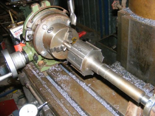
Tomorrow I'll install the magnets and epoxy them in and hopefully on monday I'll be ready to give it a decent test on my lathe. Cheers Bryan |
||||
| Dinges Senior Member Joined: 04/01/2008 Location: AlbaniaPosts: 510 |
Looks *very* nice, Bryan! So I assume you got the problems with the dividing-head figured out then? Ok... now I really hope my math was right and it doesn't cog... or else I'll be reminded by you of this for years to come, no doubt. 
Peter. |
||||
| Zeusmorg Newbie Joined: 29/11/2007 Location: Posts: 5 |
Yeah Dinges if it cogs, he'll grab is canoe and ROW to Europe just to kill you! Great looking job bryan, I can't wait to see this all completed, i get excited when my friends complete a job. |
||||
| Bryan1 Guru Joined: 22/02/2006 Location: AustraliaPosts: 2102 |
Bad news guys silly me slipped and 2 of the mags wacked together splitting them in 1/2.  Now I could still use the 2 split ones by super glueing them in place and using some SS bar to ensure they seat properly. Now the question is would that effect the overall performance or be ok. For me to order 2 new mags it will mean ordering them from the US and cost a bomb to get over here. I couldn't see any small fragments so the split was clean on both so hopefully it will ok to use them, but as this is the first time I've done this I'll appreciate any views. Now I could still use the 2 split ones by super glueing them in place and using some SS bar to ensure they seat properly. Now the question is would that effect the overall performance or be ok. For me to order 2 new mags it will mean ordering them from the US and cost a bomb to get over here. I couldn't see any small fragments so the split was clean on both so hopefully it will ok to use them, but as this is the first time I've done this I'll appreciate any views.
Cheers Bryan |
||||
| Dinges Senior Member Joined: 04/01/2008 Location: AlbaniaPosts: 510 |
Bugger! [and other more powerful expletives here] Very sorry to hear about this. And I don't like saying this... but you can't say you haven't been warned...: [quote=Dinges]You may want to order a few spare magnets. At least if you're like me and occasionally experience a mishap with them... [/quote] http://www.thebackshed.com/Windmill/FORUM1/forum_posts.asp?T ID=1390&PN=1&TPN=2 Or maybe it's one of those things each of us have to learn the hard way (I recall Bruce having had a similar problem with his F&P neo conversion). For the 10hph conversion I ordered 42 magnets even though I only needed 36. I too ended up destroying 2 magnets (by playing, not while installing them). I wouldn't repair them with superglue (or, as our mutual friend Wdyasq calls it, 'stupid glue'). Maybe with epoxy something can be done. But if it were my 2hp conversion... and considering how much time and effort I would have put into it by now... I'd bite the bullet and pull out my wallet... again. That is my view. Others may differ. And it's easy for me to say, as I won't be the one pulling out my wallet. Muttley, however, seems to enjoy your misfortune... Peter. |
||||
vawtman Senior Member Joined: 14/09/2006 Location: United StatesPosts: 146 |
Hi Bryan Not sure where you bought the initial mags tryhereand calculate shipping. Sorry to here of your misfortune I had a couple fly out of my setting tool and slam into each other but luckily none broke.The problem was i had wrong pole set and too many beers 
I have 2 without holes i would give ya or maybe Peter would be closer. That would always bug me if i had a patched up mag. Good luck to you and nice work. |
||||
| Bryan1 Guru Joined: 22/02/2006 Location: AustraliaPosts: 2102 |
Wellguys I bit da bullet and superglued those broken neo's in. I also epoxied them in so wedneday night I'll be machining the rotor and I'll put a pic up of the finished rotor. The superglue held the broken mags in place nicely and my crude but simple pole tester using a ugn5303 hall effect sensor a resistor and led worked a treat. O'well lesson learnt about handling neo's be bloody carefull. Cheers Bryan |
||||
| Bryan1 Guru Joined: 22/02/2006 Location: AustraliaPosts: 2102 |
G'day Guy's, Well after bloody hours of work I finally got the 2hp all together and tomorrow I'm off to buy some vaseline to rub all over the rotor as it will make it easier to RAM up Dinges butt. To say it cogs is a bloody understatement, I set up a 300mm rule on the output shaft and it took over 100 grams at the end of the ruler to overcome the cogging. So I'm about near $200 out of pocket and over 20 hours of work down the drain. 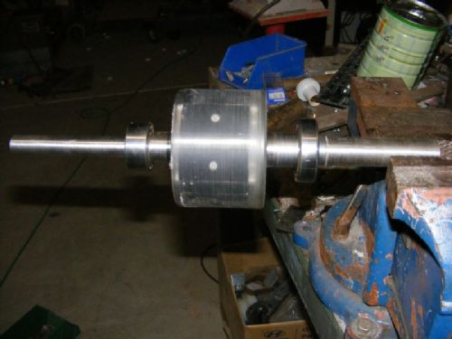
Bryan ( who is now saving up for a trip over to dyke pusher land with a greased up rotor) |
||||
| Dinges Senior Member Joined: 04/01/2008 Location: AlbaniaPosts: 510 |
Bryan, Not sure what went wrong. I've double-checked my work and I don't see any errors in it. I've used exactly the same method for my 10hp conversion (using 4.5 times as many magnets as your conversion) without even the slightest hint of cogging. Of course, this is of little consolation to you now. I'm not sure though it's a useless paperweight, as you seem to think, despite the cogging, but understand your disappointment. I will not be giving design help on the internet anymore. I've spent quite a bit of time and effort trying to help you and others. Also in your case I've had to nearly drag the information out (it still hasn't been positively confirmed by you if it actually had 36 stator slots, for example, as I asked in the beginning). In another case someone finally let out that the dimensions he gave me as the basis for calculations were not the correct dimensions (it turned out later), when it did cog some. This will have been the last time. I do not feel like I have to prove or sell this method (or even conversions) to anyone. They work for me. They worked for Zubbly. I like them. I like building them. I've never had a single one that cogged. Of course, I could've been lucky in the ~8 conversions I've made so far, but considering that JacquesM used the method (http://www.fieldlines.com/story/2004/12/26/22306/009), as well as Victor and myself, I think there's a pattern of repeatable succesful builds. The idea itself was taken from a patent ( http://www.google.com/patents?id=dTo7AAAAEBAJ&printsec=abstr act&zoom=4&dq=cogging+motor, patent nr. 4713569). I only found this patent a few months ago. Guess it shows that this method is another case of 'nothing new under the sun'. I'm sorry to hear your alternator doesn't perform as expected. All I can say is I tried to help you to the best of my ability. Peter. |
||||
| vawtman Senior Member Joined: 14/09/2006 Location: United StatesPosts: 146 |
Hi Peter This method of decogging must need to be very precise.It seems to me a mm here or a mm there could make massive difference.Peter don't let this incident get you down.You have been a great help to me and many others 
Bryan could still skew the lams like i did with "sparky" and wind it to his specs.It's fun and not that hard to do. I read just about everyone of your posts and find them very enjoyable and dedicated. Thanks from me at least |
||||
| brucedownunder2 Guru Joined: 14/09/2005 Location: AustraliaPosts: 1548 |
Hi Peter, I'm sure Bryan is just having a lend of you ,,he's an Aussie and we are a lay-back bunch of Drongo's, so his comments are probably not meant to offend you. I'll smack him over the head with a rotten leg of lamb when we meet.. And,, of course we all know what he's gunna do with that jar of vasaline,,he'll whack it on his rotor ,,thats for sure... Cheers, ol mate.. Bruce.. Bushboy |
||||
| vawtman Senior Member Joined: 14/09/2006 Location: United StatesPosts: 146 |
I recall getting into an arguement with Wyasdag(ron) and Jaquesm about this on IRC.They kept bringing up windings and i kept bringing up the actual causes of cogging. If all the mags are sharing a tooth at times i would guess the motor would have no cog.Say one covered the rotor with mags no gaps more than the tooth fingers. The thing that concerns me is there would also be no pole separation maybe cancelation is not that big a deal. Hmmm maybe we could put a steel dummy mag in that area slightly magnetized by the leakage from the surrounding mags.Sorta a shock absorber 
I know i'm nuts but havin fun |
||||
| Bryan1 Guru Joined: 22/02/2006 Location: AustraliaPosts: 2102 |
Well guy's, As anyone can imagine doing a job like this for the first time and I ensured i got the angle and depth of each rotor slot within 0.001" and made several pass's over each slot with 0.002" cuts to ensure I didn't have any errors. Below is a pic with the output cover taken off and YES it does have 36 slots. From what I can see from the pic compared to Dinges cad drawing they are the same. 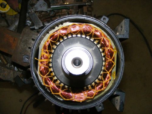
Peter I did talk in jest with you in IRC if this thing cogged what I'd do and if you remember you did offer to bend over So lighten up mate This isn't about laying blame on anyone and you could imagine how jacked off I was when after I put it all together it cogged.
Anyway time to go do a lathe test and see what figures I comeup with and hopefully with my current 3 metre blades with the high twist they will be able to overcome the cogging. Cheers Bryan |
||||
herbnz Senior Member Joined: 18/02/2007 Location: New ZealandPosts: 258 |
Hi Bryan Just a thought I see you have a winding in, you have not got connected in any way ? particularly in delta as with phase shift due to displaced magnets you would get circulating currents would feel like cogging. Herb |
||||
| Janne Senior Member Joined: 20/06/2008 Location: FinlandPosts: 121 |
Sorry to hear it didn't work as planned. Though I think we can't blaim dinges on this , I made a drawing about the situation and in paper it looks just the way it should, the cogging effect of each pole should cancel each other out. 
So what comes to my mind is 2 options, some machining error (unlikely?), or the broken magnet messing it up somehow, although i can't figure how it would affect it. there is also the matter of different leakage flux on the poles, because of the one large gap on the magnets, but if it works for dinges in even a larger conversion, why it wouldn't work in here? If at first you don't succeed, try again. My projects |
||||
| Page 1 of 2 |
|||||
| The Back Shed's forum code is written, and hosted, in Australia. | © JAQ Software 2026 |
