
|
|
Forum Index : Windmills : Is the F&P 1" shaft adeuqate for ax flux?
| Page 1 of 2 |
|||||
| Author | Message | ||||
imsmooth Senior Member Joined: 07/02/2008 Location: United StatesPosts: 214 |
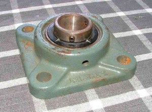
I need to redesign my weldment and would like to use the F&P 1" shaft and bearings. Will this be adequate to hold the axial flux design? The blades/hub/rotors will probably weigh 50lbs and will be about 1/2" from the bearing support. The shaft gets thinner than 1" near the nut. I am hoping others have experience with the weight the shaft can support at rpms of 500-600. |
||||
| GWatPE Senior Member Joined: 01/09/2006 Location: AustraliaPosts: 2127 |
Hi imsmooth, I would not use the bearing assembly from the F&P. There is not enough support for the outer ring of the front ball race. The shaft may be strong enough. The shafts in Phills quad survived when all else was totalled. In my AxFx design one rotor only is attached to the bearing outer housing, and the main rotor loading is positioned directly over the main bearing. I do not think the open style design dual rotor AxFx system is the best for a windmill. I think that it is OK for the original intention, to provide a cheap alternative power generation source in poorer countries where resources are slim. I would want any windmill alternator/blade/yawbox/furling assembly to be good for 10-20 years on the mechanicals. Time will tell if mine is up to it as well. Gordon. become more energy aware |
||||
| Gizmo Admin Group Joined: 05/06/2004 Location: AustraliaPosts: 5182 |
I agree with Gordon the standard F&P bearing is not the best option for long reliable duty. I've used the 56205 double row bearing and its matching carrier F205 for a few projects now, its a tough little bugger and matches the F&P shaft. 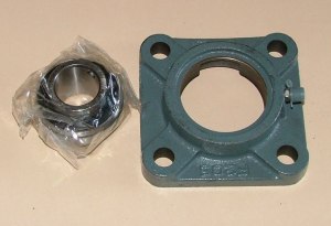
Glenn The best time to plant a tree was twenty years ago, the second best time is right now. JAQ |
||||
| imsmooth Senior Member Joined: 07/02/2008 Location: United StatesPosts: 214 |
Ok. I plan on the axial flux alternator design, and I like my idea for the disc brake system. How can I incorporate the two? Using the design on Otherpower the Dexter Hub/spindle does not allow the transmission of power down a shaft. This is why I liked the spindle for the F&P. Do you have any good pictures showing how this might be done? How about this idea. I can redesign the assembly to allow the weight of the rotor to sit on the 1" shaft. I can then use a disc plate with a spline pattern in the center. This disc will in turn connect to the magnetic rotor. If I brake the other end this will slow the spline-disc, which will brake the rotor, whose weight is on the 1" section of shaft, and not the 3/4" section. If this idea is not good, do you guys have another suggestion? I will even use a larger shaft as long as you have an idea how I can reliably connect it to a disc brake. |
||||
| domwild Guru Joined: 16/12/2005 Location: AustraliaPosts: 873 |
Just to be extremely finicky: the shaft is precisely 25.0 mm so do not order any imperial bearings. One inch is 25.404 mm, if I remember that figure correctly. The shaft is stainless steel. I remember the Finn hvirtane on fieldlines saying that prop dia. to shaft dia. should be 100 : 1. So a 3 m dia. or 3000 mm dia needs a 30 mm shaft. He may talk about mild steel, so you are safe with stainless. Taxation as a means of achieving prosperity is like a man standing inside a bucket trying to lift himself up. Winston Churchill |
||||
| imsmooth Senior Member Joined: 07/02/2008 Location: United StatesPosts: 214 |
Thanks Dom. Yes, I know it is 25mm as that is how I ordered my bearings. I guess to be precise I should use the correct measurements. So are you saying the F&P shaft should be ok? Please distinguish between the two options. I can easily have a steel disc with the spline pattern and rest the rotor/blade/hub on the spline. The thinnest measurement is about 0.75". Will this be adequate? Or, do I need to work it to rest the rotor/blade/hub on the 25mm shaft? This will take more work and I have to figure out how to work in an emergency disc braking system. If I have the rotor diameter 1.5" larger I could possibly have the caliper brake the outer rim of the rotor. However, I don't have access to a water-jet cut disc larger than the one provided by the Dans at Otherpower. |
||||
| GWatPE Senior Member Joined: 01/09/2006 Location: AustraliaPosts: 2127 |
Hi imsmooth, What benefit do you think a disk brake will be on an AxFx mill? The windings alone should present more than enough stopping power when shorted. I think that if you need a disk brake, then there is a problem with winding resistance, or magnets. Money would be better spent on magnets and copper wire than a disk brake. Oztules had no problem stopping his windmill with 4m rotor diameter and putting out 4-5kW by shorting the windings. For some reason do you think that the rotor has to be stationery to be braked sufficiently? Do you think that the stator may fail and then the mill will be difficult to stop. Rest assured, that in the early days of my F&P mill, overdriven with 3m rotor, that I was able to lower my mill at night during a storm [30-40knot winds], when the mill started with the electric brake ON. As soon as the windmill is not vertical, the tail tries to furl the rotor and the machine slows quickly. I now set the furling so that even if the mill becomes unloaded, that the mill will still survive. Orientation of the guys and the mill lowering away from the predominant storm wind direction will be useful as well. I would not attempt to get a brake caliper onto the plates that the magnets are attached to. Gordon. become more energy aware |
||||
| imsmooth Senior Member Joined: 07/02/2008 Location: United StatesPosts: 214 |
Ok. Can you clarify one of the first posts: If I use the F205 carrier, can I use the F&P shaft for a 10' machine if I have the weight on the 25mm portion of the shaft? I will have two bearings, well supported, holding the shaft, and the F205&bearing connected to the shaft and one of the magnetic rotors. I could even then have all-threads coming out to connect to a disc on the spline to transmit the torque. |
||||
oztules Guru Joined: 26/07/2007 Location: AustraliaPosts: 1686 |
Imsmooth, If you build the Dans 10' machine using the round magnets, you will not need the brake. It will brake on command even in a gale.... probably when your original brake would prove to be under extreme pressure to stop it. I would not use the square magnet version. It is under designed. If you also design the furling to be sensible, you will have no heat problems, no braking problems, and a sturdy unit. It will bear no resemblance in any way to your F@P turbine. They are very different animals. Mine has 4m blade, 24 round n45 mags, and stops when I tell it... even when it has >10kw wind inputs. It is very very controllable. .........oztules Village idiot...or... just another hack out of his depth |
||||
| imsmooth Senior Member Joined: 07/02/2008 Location: United StatesPosts: 214 |
Oztules, Thank you. A few things, and the first something that might interest you. I am recarving some blades using the chainsaw, and I am going to create a webpage dedicated for the topic for others to see. I am going to take more video and pictures of the whole process. Any suggestions? Would you like to write something up and I can include your text and/or pictures on the site? As far as the rotor I am going to build...I order N48 2" disc magnets. I just need to figure out what size wire I am going to use to match the inverter I plan to purchase. I will have to make some test coils. You and others talk about furling at the right point. I guess this is a matter of how much heat the stator can take. How do you determine what is too much? If I look at the ampacity of a gauge of wire there is a value for transmission and for chassis. Transmission, which is much higher, assumes the wire is open and not bundled or enclosed. There is a big difference between the two values. For example, 18g has chassis of 2.3A and transmission of 16A. Does this mean for short times I could go 10A or 12A? |
||||
| GWatPE Senior Member Joined: 01/09/2006 Location: AustraliaPosts: 2127 |
If you are playing a numbers game [want to quote numbers for possible better sales exposure], then you will enable furling to allow the windmill to survive a storm only. If you are more conservative and want a windmill to produce useful power most of the time, and still some power in storms, you will design for furling at a much lower windspeed. It really is up to you. If your winds are mainly 0-8m/s, with storms <10 times per year of winds >10m/s then it is not much use having to design for 10x power levels. Better to have a docile machine that works really well 80% of the time, with the peaks of storm power just limited by the furling in a conservative manner. I am sure my new AxFx alternator will have some outragous specifications of potential power, but I will still use the same furling. A potential 4-5kW alternator restricted to approx 1kW max power. I could not hope to use the full output power without 5x bigger battery, or 5x bigger grid inverter and of course 5x bigger protection systems. You have to decide what you want the mill to do first. Gordon. become more energy aware |
||||
| Janne Senior Member Joined: 20/06/2008 Location: FinlandPosts: 121 |
Hi, That rule of thumb applies for good quality draw shaft steel. That is a good value if you really want to play safe, but i guess a little thinner is ok too. Mild steel should be ok too but I would be tempted to use a little thicker stock in that case. Welding also should be avoided in the rotor shaft. If at first you don't succeed, try again. My projects |
||||
| imsmooth Senior Member Joined: 07/02/2008 Location: United StatesPosts: 214 |
THanks Gordon. However, I am going to use MPPT, so I will be able to draw good power in low and high winds. I just have to pick a point so the rotor doesn't over-spin. Do you think 35mph winds or 500rpm is reasonable? Janne, I tried looking for a reference for this rule of thumb. Any suggestions? |
||||
| GWatPE Senior Member Joined: 01/09/2006 Location: AustraliaPosts: 2127 |
Hi imsmooth, MPPT makes the problem with inverter sizing and economic returns on investment less viable. If you plan on an installation in suburbia for personal use, I see a poor use of capital equipment costs. If you are designing for an optimum wind site, then capital equipment costs would be repaid in an economic time. You may wish to elaborate on the MPPT system you intend using. Gordon. become more energy aware |
||||
| imsmooth Senior Member Joined: 07/02/2008 Location: United StatesPosts: 214 |
Aurora Power-One 3.6kw unit. 16 programmable points. 50-600v input voltage. awaiting UL approval ~$1900USD + $60 shipping Other choice is by Ginlong 2.0kw. 30-750v input. over 30 programmable points. awaiting UL approval. ~$99USD + $250 shipping I know this adds to cost, but this is something I want to do, more for an environmental statement. My return will take some time, but I do get some good winds in the winter. |
||||
| Janne Senior Member Joined: 20/06/2008 Location: FinlandPosts: 121 |
Hi, I haven't seen this mentioned on the internet. I picked the rule from a book "Winpowerhobbyist's guide" (written in finnish), written by some of the builers of big heating wind turbines in Finland. On the next page is a photo from a shattered 60mm shaft that previosly held the 11m rotor in the air... serving as a visual reminder ;) If at first you don't succeed, try again. My projects |
||||
| imsmooth Senior Member Joined: 07/02/2008 Location: United StatesPosts: 214 |
The rotor was 11M in diameter on a 60mm shaft?! That is thin. Gordon, since I will now use an electric brake, will a 32A disconnect switch be sufficient for a 10' machine? I'm going to rig it to short the lines. The coils will be wound to favor voltage over amperage. I am hoping for 10A at full power with a voltage in the 250v range. |
||||
| GWatPE Senior Member Joined: 01/09/2006 Location: AustraliaPosts: 2127 |
As an environmental statement, I can understand solar, or hydro, or vegoil generator, but not a windmill in the manner you intend. I will elaborate. In the solar, hydro and vegoil systems, you can size the system to pretty well fully load to the maximum generator capacity for the energy source for a major part of the operation time. A windmill does not offer this type of energy stream. I would only size for the average energy that is expected to be produced 80% of the time. In the other 20% will be significant storm events where the highest wind energy may be available. It is better to still only harvest the average energy during these storms. If you size for the maximum energy that could be produced, then you will have paid for equipment that will be probably operating at about 1/8 or less capacity most of the time. I used to chase the maximum power, for comparison purposes. I now furl limit the top end power, and efficiently harvest the wind energy in the lower and mid power levels. The alternator is still the same, but I use an inverter that is only 1/4 of the size. This only cost 1/4 as much and is operating up to 75% of capacity on most days, instead of a few total hours a year. If your intention is to harvest every portion of wind energy passing your location, then this will require equipment that is inefficiently used for most of the time and this in not really good from an environmental perspective. My testing has shown that an optimum system is a large rotor size to harvest modest power in very low winds [<5m/s]. A large alternator for high efficiency electrical harvesting [not sure how to quantify this]. Furling set for the maximum winds that occur 80% of the time. An inverter sized to the maximum electrical energy at the furling limits. If you can provide some measured windspeed data for your location, [daily average windspeed, maximum daily windspeed, etc over a whole year], then this would help. Gordon. become more energy aware |
||||
| oztules Guru Joined: 26/07/2007 Location: AustraliaPosts: 1686 |
I partially agree with Gordon on this one. Once you get into axial flux devices with low resistance, even when you furl low, you will get instances in strong winds where the furling is confused and current and voltage will rise frighteningly for very small periods. To the stator this is no big deal, as it will probably be only for a few seconds or tens of seconds, until it rights itself. An example of this is my mill. It is set to furl at about 700w, even though it can do lots more. It is stall regulated as well because it is designed for 48v, but driving a 36v battery bank.. so well mismatched  ....But, it we have a 40 mph blow, and the wind shifts in gusts rapidly, the furling will not catchup in real time, and currents exceeding 45 amps will come through for very short periods. With batteries limiting the voltage, this is bad enough... but no damage. With a inverter trying to contain it, the voltages will shoot up to in excess of 140-150v@45A (the blades will not be stalled and the power runs rampant without the batteries anchoring them down. An MPPT inverter will let it run up) ....But, it we have a 40 mph blow, and the wind shifts in gusts rapidly, the furling will not catchup in real time, and currents exceeding 45 amps will come through for very short periods. With batteries limiting the voltage, this is bad enough... but no damage. With a inverter trying to contain it, the voltages will shoot up to in excess of 140-150v@45A (the blades will not be stalled and the power runs rampant without the batteries anchoring them down. An MPPT inverter will let it run up)
You can see that you need a serious crowbar to save the electronics if your starting with 250v... a quick run up with 20kw in the blades will be hard to deal with electronically before the furl takes over and sensibly limits it.... so beware chasing the top 20% winds as Gordon has iterated. However, if you do wish to do that, then build a breezy or similar. It will only run for 20% of the time usefully, but will generate more in a year then the other 80% of the time. It will be bullet proof electrically, as no electronics are there to suffer the big outputs when they arrive.... it's all balancing in the end. But the axials are definately not current limit devices like the F@P. On the blades thing.... do as you wish. You do it better than me so I don't wish to cramp your style. Best of luck with it 
.........oztules Village idiot...or... just another hack out of his depth |
||||
| imsmooth Senior Member Joined: 07/02/2008 Location: United StatesPosts: 214 |
I will take both your comments into consideration. I hope I am not overestimating my linear shunt inverter, but it performed remarkably well during the storm. It came on and off perfectly, and capped the voltage exactly where I set it, dumping the excess current into my resistor bank. I guess I will need to double my resistor bank. Right now it can easily take 1600W. My mosfet bank is sized to take 4kw under perfect cooling conditions. I know I won't get 4kw, but I have a built-in fan cooling system over the oversized finned heat sinks. I will have a place to start once I make my rotor and can test some coils. |
||||
| Page 1 of 2 |
|||||
| The Back Shed's forum code is written, and hosted, in Australia. | © JAQ Software 2026 |
