
|
|
Forum Index : Microcontroller and PC projects : I've now jumped on the PICO2 train...
| Page 1 of 2 |
|||||
| Author | Message | ||||
Grogster Admin Group Joined: 31/12/2012 Location: New ZealandPosts: 9995 |
I have some on order. 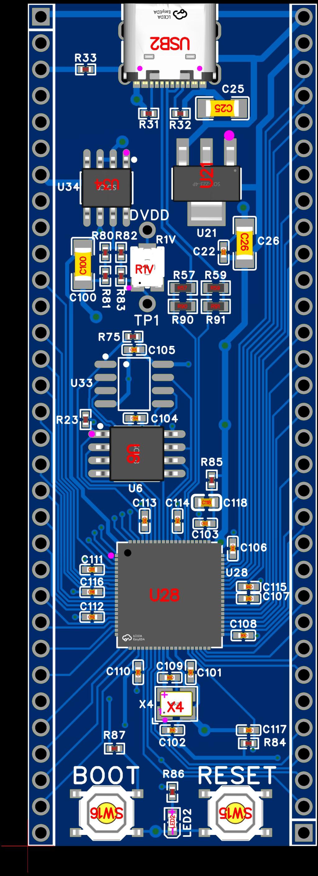 This module looks very nice indeed. Good job, Peter.  As with everyone else's orders, the PSRAM chip was unavailable, so I just left it off. I HOPE....I can get some time to play with this new module. I am very busy at work these daze.....  Smoke makes things work. When the smoke gets out, it stops! |
||||
Bryan1 Guru Joined: 22/02/2006 Location: AustraliaPosts: 2161 |
Grog's if you one spare I'll buy one off you mate Cheers Bryan |
||||
| Bleep Guru Joined: 09/01/2022 Location: United KingdomPosts: 817 |
Make sure you set up the R1V pot before you power anything on. |
||||
| matherp Guru Joined: 11/12/2012 Location: United KingdomPosts: 11645 |
The pots seem to come mid-range which gives a voltage of just over 1.4 - perfectly safe. I just power the boards up and then with a multimeter across DVDD and GND adjust to 1.3. The board is designed so that even with the pot full scale it should be safe (1.8V) - others have run the chip at that without issue |
||||
| PhenixRising Guru Joined: 07/11/2023 Location: United KingdomPosts: 2005 |
Started laying out a carrier board. DIL is soo nice. |
||||
| Grogster Admin Group Joined: 31/12/2012 Location: New ZealandPosts: 9995 |
I will ensure pot is mid-range first, then do the power check thing. I have to do a bit more research on Peter's original thread. I can't remember what the purpose of the little trimmer is, but I am sure it is there for good reason. None of the other boards have it, so perhaps it is specific to the 2350 chip or something - I will go do a bit more reading to find out. JLC website DID moan that the oscillator and caps were NOT those specifically stated by Raspberry PI Org that you are supposed to use, but I basically ignored it, assuming Peter knows what he's doing with PI boards now, and I have also seen posts from others who have had these boards made, and they obviously start up fine, so.... Smoke makes things work. When the smoke gets out, it stops! |
||||
| Grogster Admin Group Joined: 31/12/2012 Location: New ZealandPosts: 9995 |
Yes, I ordered ten units, so I will have a few spares - I'll only be playing with one module to start with. I may well put them up on my website, so long as Peter is happy with the state of the design etc, and if other members think that would be something they would like me to do. Smoke makes things work. When the smoke gets out, it stops! |
||||
| Bryan1 Guru Joined: 22/02/2006 Location: AustraliaPosts: 2161 |
Thanks Grog's when your ready to send one over just PM me with the cost and I'll make the payment straight away. |
||||
| robert.rozee Guru Joined: 31/12/2012 Location: New ZealandPosts: 2541 |
is the unused end of R1V tied to the wiper? i'd be interested in seeing both sides of the PCB with parts unpopulated so all tracks are visible. cheers, rob :-) |
||||
| matherp Guru Joined: 11/12/2012 Location: United KingdomPosts: 11645 |
Grogster et al I have done a trivial update to include GPIO numbers on the top silkscreen of the board. No other changes. The board as you have ordered seems rock solid. Pico2350DILV1.2.zip 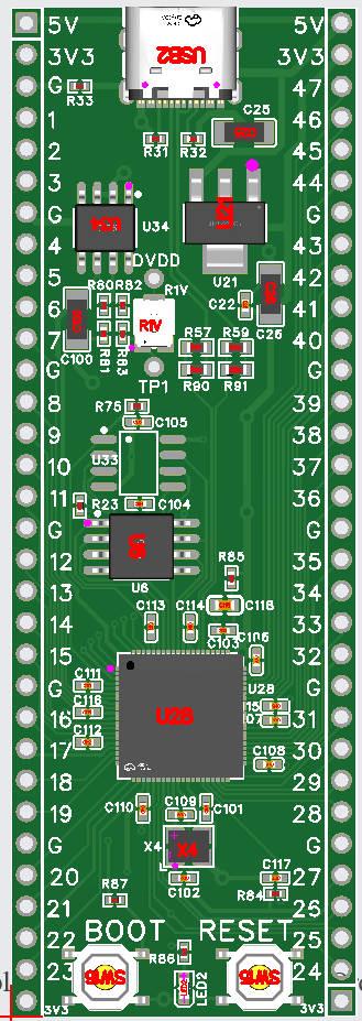 Edited 2025-06-14 17:17 by matherp |
||||
| Grogster Admin Group Joined: 31/12/2012 Location: New ZealandPosts: 9995 |
Excellent. I have yet to test my units as ordered, but if Peter is happy(and it seems he is) with the stability of this layout, I will PROBABLY offer these for sale on my website. Shipping world-wide. Smoke makes things work. When the smoke gets out, it stops! |
||||
| Grogster Admin Group Joined: 31/12/2012 Location: New ZealandPosts: 9995 |
One of the things I want to do, is design a carrier board that has HDMI. PhenixRising has already indicated this is in progress, so rather then double-up, perhaps the member can elaborate on what they are going to have on their carrier board? No sense in re-inventing the wheel..... Smoke makes things work. When the smoke gets out, it stops! |
||||
| PhenixRising Guru Joined: 07/11/2023 Location: United KingdomPosts: 2005 |
Hi Grogs, Mine is purely for machine interfacing. -16 buffered ins -16 buffered outs -2 MC3486 line receivers -2 4050 level shifters -1 op-amp for analog out -1 MAX3491 for multidrop, FD RS422. etc.... |
||||
| Grogster Admin Group Joined: 31/12/2012 Location: New ZealandPosts: 9995 |
My boards have arrived. 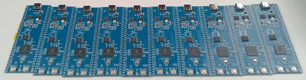 I hope to have a play around with one of them over the weekend. Smoke makes things work. When the smoke gets out, it stops! |
||||
| PhenixRising Guru Joined: 07/11/2023 Location: United KingdomPosts: 2005 |
 |
||||
| Grogster Admin Group Joined: 31/12/2012 Location: New ZealandPosts: 9995 |
OK, I have my first PICO2 up and running, and white "Heartbeat" LED blinking away there happily. Can someone just briefly explain WHY there was a need for the wee trimmer, and setting it to 1.30v - which I have done, BEFORE I loaded the MMBASIC firmware. I am sure this has been covered before, but I have been very busy lately, and have not had the time to read each and every thread or post, so a quick pointer as to the purpose and need for this trimmer would be fantastic.  Smoke makes things work. When the smoke gets out, it stops! |
||||
| Volhout Guru Joined: 05/03/2018 Location: NetherlandsPosts: 5994 |
Hi grogster, In short: RP designed a switch mode power supply for the core voltage INSIDE the RP2350B. That switcher has possibility to adjust the core voltage to support over clocking. But.. RP found out that the switcher is sensitive to noise, and specific noise generated from the coil that the switcher uses. Polarity of the coil (how it is wound) is key. And since there is no polarity indicator on small coils, problems are to be expected. Hence Peter decided to avoid the issue, and use an external linear regulator for the core voltage. And if you want to "overclock" you have to set it for 1.3V (normal core voltage is 1.1V for 150MHz). That is the short story, Volhout Edited 2025-06-20 16:52 by Volhout PicomiteVGA PETSCII ROBOTS |
||||
| JohnS Guru Joined: 18/11/2011 Location: United KingdomPosts: 4352 |
IIRC, the faster you want to go the higher the voltage needed. John |
||||
| Mixtel90 Guru Joined: 05/10/2019 Location: United KingdomPosts: 8965 |
"These go to 11" :) (Tune for maximum smoke) Mick Zilog Inside! nascom.info for Nascom & Gemini Preliminary MMBasic docs & my PCB designs |
||||
| Grogster Admin Group Joined: 31/12/2012 Location: New ZealandPosts: 9995 |
@ Volhout: Thanks a bunch. Explains it exactly. EDIT: Should I be setting the default core voltage to 1.10v then? 1.30v might be needed for HDMI support etc. Edited 2025-06-20 17:28 by Grogster Smoke makes things work. When the smoke gets out, it stops! |
||||
| Page 1 of 2 |
|||||
| The Back Shed's forum code is written, and hosted, in Australia. | © JAQ Software 2026 |
