
|
|
Forum Index : Microcontroller and PC projects : Versatile remote IO design
| Page 1 of 2 |
|||||
| Author | Message | ||||
| Mixtel90 Guru Joined: 05/10/2019 Location: United KingdomPosts: 8965 |
Something that I've been considering for some time. This could be used with anything that can send and receive 3V3 I2C. The board is small enough to get two out of a 100mm square of PCB material. 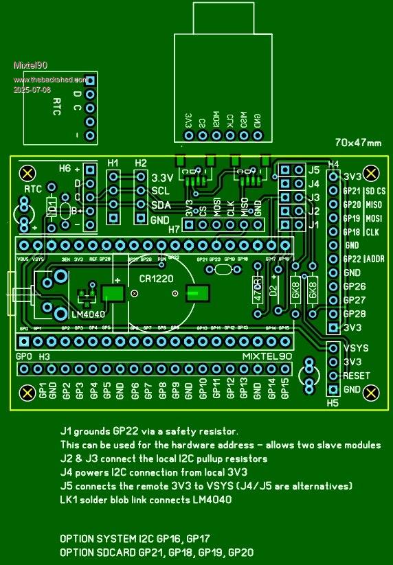 Any of the Pico pin-compatible devices can be used but a few of the modules, such as the YD-RP2040, are slightly wider and there might be mechanical considerations if the SD card or RTC is fitted. This can run stand-alone or as a remote IO board. By default it communicates over I2C, but it's easy to use multi-drop COM instead by adding diode D2. Communication pullup resistors are optional. If I2C is being used for communication: A mini RTC can be used if required, with an optional additional battery. A SD card module can be added if required. Unless the SD card module is fitted all GPIO pins apart from the two allocated to communication (GP16 & GP17)are available to the user. The power chain is configurable. 5V via USB. 3V3 via the communication supply. If using this as a master module it can power the communication supply at 3V3. VSYS is accessible on H5. There is already some software support for remote IO. Some time ago @lizby produced some routines that might be used with this board. Sorry, I can't find them at the moment. You could easily connect another SPI device, sharing the port with the SD card and using GP22 as a select line. GP26-GP28 are available on the same connector. Mick Zilog Inside! nascom.info for Nascom & Gemini Preliminary MMBasic docs & my PCB designs |
||||
| PhenixRising Guru Joined: 07/11/2023 Location: United KingdomPosts: 2005 |
Hi Mick, Have you played with Pico-to-Pico I2C and if so, how is the performance? |
||||
| Mixtel90 Guru Joined: 05/10/2019 Location: United KingdomPosts: 8965 |
I tried it a while ago. Just an experiment to make a I2C game controller. Actual data transfer is very reasonable, but it will depend on your protocol more than anything else. I wouldn't recommend doing remote IO any faster than 100kHz due to cable length issues as it's really designed for on-board communication. The other problem is that I2C isn't buffered so you have to work round that. I used about 600mm of telephone wire and 100kHz. The controller was handled by the master asking it for registers or register sets, so you might only ask for the buttons as a byte (very fast) or both of the X and Y positions of the analogue joystick - slower obviously. The controller used a RP2040-Zero. Mick Zilog Inside! nascom.info for Nascom & Gemini Preliminary MMBasic docs & my PCB designs |
||||
| Volhout Guru Joined: 05/03/2018 Location: NetherlandsPosts: 5994 |
Hi Phenix, Last weeks spend again a lot of time debugging a test system using I2C for some sensors. Lessons learned (again) : Don't use I2C crossing boards (flat cable) in an electrically dirty environment (near a 11kW 3phase motor drive). I2C on a PCB with good ground plane is fine. But as soon as you leave the board the open drain (pullup impedance) makes it vulnerable. And there is simply no good way to filter this out (capacitors/common mode chokes). If you need I2C then use one of those serial-I2C convertors, make the cable run on serial (RS422) and convert to I2C near the I2C device. And when you implement I2C in industrial system, it is almost certain I2C errors will occur. Make sure your software can handle I2C errors. SCL stuck low is a nasty one, most cases require a hard reset of the I2C device (slave). SDA stuck low can be repaired with 9 clock pulses on SCL. Implement error handling from the start !!! Do not wait until you are hit by it in the field. Then it is too late to implement the reset of a device (*). Volhout Most I2C devices can be reset by removing Vdd, waiting, and re-applying Vdd. This only requires to switch individual device Vdd, no need for extra RESET line. You can also power low power I2C devices from the output of a logic gate (that acts to switch Vdd). P.S. There are I2C bus buffers that can communicate I2C with low resistance pullups. That improves somewhat. It is not fail proof though. Edited 2025-07-08 21:22 by Volhout PicomiteVGA PETSCII ROBOTS |
||||
| Mixtel90 Guru Joined: 05/10/2019 Location: United KingdomPosts: 8965 |
All very true! I'm not pretending that this board is industrial gear, more a way of adding extra IO to a Pico mounted somewhere nearby. For industrial stuff I'd only use RS485 or, in severe cases, opto. That's become a lot cheaper than it used to be, especially if the distance isn't too great for plastic fibre. For this particular board you might get improved performance using multi-drop COM, purely because the COM ports are buffered. It's still only local though as the pullups are only resistive, not active. You also can't use it if the RTC is fitted as that assumes a I2C bus. I could have given the communication lines their own GPIO pins and put the local I2C stuff on another pair, but that's using pins that might be required for something else. Oh, a bit of rearrangement and the YD-RP2040 will fit now (preferably shorting pins 39 and 40). GP23 and GP29 come out to pads near the RTC battery. . Edited 2025-07-08 21:49 by Mixtel90 Mick Zilog Inside! nascom.info for Nascom & Gemini Preliminary MMBasic docs & my PCB designs |
||||
| PhenixRising Guru Joined: 07/11/2023 Location: United KingdomPosts: 2005 |
Hi guys. I am more than happy with multidrop serial (4-wire) for external communications. No. I was wondering about multiple PicoMites on the same motherboard because we only have two UARTS. I don't have a need for this but it's one of those things that I was thinking about. I was reading an article, recently about the not-so-great aspects of I2C. It hasn't discouraged me because my use would be very simple. I might just set up a couple of my DIL modules and have a play. But as stated, not needing anything at this point. |
||||
| Mixtel90 Guru Joined: 05/10/2019 Location: United KingdomPosts: 8965 |
Oh, they'll almost certainly work fine for that. I did a design ages ago, the PicoMite Pear, which was virtually that. It gives the option to link the Picos in different ways so that you can experiment. The RP2040 Datasheet shows some examples of using a PIO as an extra COM or I2C port. They wouldn't be natively supported by MMBasic though. Mick Zilog Inside! nascom.info for Nascom & Gemini Preliminary MMBasic docs & my PCB designs |
||||
| PhenixRising Guru Joined: 07/11/2023 Location: United KingdomPosts: 2005 |
Some things really mess with my head  So MATH.PID runs at the highest interrupt priority and I use a 1mS rate. What happens when it coincides with an I2C communication. Is there a risk of losing characters? |
||||
| Mixtel90 Guru Joined: 05/10/2019 Location: United KingdomPosts: 8965 |
Almost certainly as I2C isn't buffered. However, if you are using a proper protocol the error will be detected and the I2C message resent. :) Even at 100kHz I2C will be shifting bytes (not bits) at over 10x the speed of MATH PID. Mick Zilog Inside! nascom.info for Nascom & Gemini Preliminary MMBasic docs & my PCB designs |
||||
| PhenixRising Guru Joined: 07/11/2023 Location: United KingdomPosts: 2005 |
Yeah I thought about setting a flag at the end of the MATH.PID callback before doing something else that relies on interrupts. |
||||
| Mixtel90 Guru Joined: 05/10/2019 Location: United KingdomPosts: 8965 |
Just detect I2C errors with a checksum or CRC and resend if it fails. I2C actually does have a receive buffer but it's not handled in hardware like the COM one is. The thing to do with I2C is keep messages as short as possible. You can send a lot of them, that's no problem, but short messages are more robust. That's how it was designed to work. Mick Zilog Inside! nascom.info for Nascom & Gemini Preliminary MMBasic docs & my PCB designs |
||||
| Volhout Guru Joined: 05/03/2018 Location: NetherlandsPosts: 5994 |
Phenix, It depends on how well the MMBasic code is written. But almost certain, you would not loose any I2C data, since the I2C protocol is byte based. And the byte transfer happens in hardware. But. When you are planning to run multiple PID's that are fed from multiple I2C data streams, you may want to lower your expectations about the 1ms rate. A single...maybe... with very tuned coding. But multiple... most certainly not. MMBasic is interpreted basic. The PID will run. The I2C communication will run. But there is a lot of "glue coding" that has to happen as well. Convert the I2C bytes to 64 bit numerics (float or integer), convert the output of the PID to a PWM or DAC or whatever. It all sounds simple (and it is) but for multiple channels it multiplies. In average a pico can run 50k-100k commands per second. But if you want to run 4 PID's in 1ms, that is 12-25 basic commands per PID. As an example (lets assume you get 4 bytes encoder position from I2C in array x%) pos! = x(0) + 256*x(1) + 65536*x(2) + 16777216*x(3) if pos!>2147483647 then inc pos!,-4294967296 Just converting that to a float for PID takes 0.18 ms (positive pos!) or 0.24 ms (make pos! negative) Maybe this can be done faster and simpler (phil99 will most likely jump on this one) but the essence remains. Multiple PID at 1ms.. not likely. Volhout Above timing is taken from a RP2040 running 252MHz, 6.00.02 MMBasic. But maybe there is a solution running the PID on the Quadrature decoder Pico. One PID per decoder should be do-able. Then the I2C output would be the PWM value for the servo. And through I2C you would feed it the new set point (and at startup the PID parameters). Distributed CPU power.. haha.. Edited 2025-07-09 01:17 by Volhout PicomiteVGA PETSCII ROBOTS |
||||
| PhenixRising Guru Joined: 07/11/2023 Location: United KingdomPosts: 2005 |
Hi Harm. This isn't for any of that stuff, I have all that figured out. BTW: I normally use STR2BIN and BIN2STR. Although 4 PIDs are doable on a single PicoMite, I have decided to dedicate A PicoMite per axis. I can still handle very tight interpolation, even on a distributed system. Different topic: I have heeded your advice to pull-down the outputs of the Micrel 2981. It has a leakage current of 200µA which isn't a problem for what I'm driving but why not get rid of it. Thanks for the heads-up  |
||||
| PhenixRising Guru Joined: 07/11/2023 Location: United KingdomPosts: 2005 |
dim integer mynm, fini dim string mn mynm = 1234567 timer=0 for i = 1 to 1000 mn = bin2str$(int64,mynm) mynm = str2bin(int64,mn) next fini = timer print fini |
||||
| lizby Guru Joined: 17/05/2016 Location: United StatesPosts: 3816 |
62 on a Pico 2 PicoMite, Armmite F4, SensorKits, MMBasic Hardware, Games, etc. on FOTS |
||||
| phil99 Guru Joined: 11/02/2018 Location: AustraliaPosts: 3322 |
Reducing spaces then shortening variables. PicoMite MMBasic RP2040 Edition V6.00.02 CPUSPEED 378000 KHz > dim integer mynm=1234567, fini :dim string mn > timer=0:for i=1 to 1000:mn=bin2str$(int64,mynm):mynm=str2bin(int64,mn):next:fini=timer :? fini;" mS" 40 mS > > dim integer m=1234567, f :dim string n > timer=0:for i=1 to 1000:n=bin2str$(int64,m):m=str2bin(int64,n):next:f=timer :? f;" mS" 36 mS PicoMiteVGA MMBasic RP2350A Edition V6.00.02 OPTION RESOLUTION 800x600 @ 360000KHz > dim integer m=1234567, f :dim string n > timer=0:for i=1 to 1000:n=bin2str$(int64,m):m=str2bin(int64,n):next:f=timer :? f;" mS" 27 mS > Edited 2025-07-09 09:19 by phil99 |
||||
| Volhout Guru Joined: 05/03/2018 Location: NetherlandsPosts: 5994 |
Hi phenix, phill, Please explain to me who you use STR2BIN and BIN2STR to convert a signed 32 bit integer supplied in an integer array x%(3) to a signed 64bit integer (or float). I understand you could replace the array x%(3) with a string (x$ length 4) since I2C READ supports a string array. But I do not see how the sign moves from 32 bit to 64 bit using STR2BIN and BIN2STR. Eager to learn... Regards, Volhout Edited 2025-07-09 17:28 by Volhout PicomiteVGA PETSCII ROBOTS |
||||
| PhenixRising Guru Joined: 07/11/2023 Location: United KingdomPosts: 2005 |
Ah, not related, for me. In my case, 32 bits of encoder position is more than enough. Out of all of the commercially available motion-controllers, I know of only one that has a 64-bit range. However, I did experiment with this and here's my method: DIM cn32 AS integer ' 64-bit variable DIM pr32 AS integer DIM roct AS integer ' roll-over counter DIM cn64 AS integer dim fin as float pr32 = 0 roct = 0 cn64 = 0 ' Read the current 32-bit counter value 'counter32 = ReadCounter32() timer=0 for i = 1 to 1000 cn32 = 4294967292 IF cn32 > 2147483647 THEN cn32 = cn32 - 4294967296 ' 2^32 END IF IF cn32 < pr32 - 2147483648 THEN roct = roct + 1 ELSEIF cn32 > pr32 + 2147483648 THEN roct = roct - 1 END IF cn64 = (roct * 4294967296) + cn32 pr32 = cn32 next fin=timer ' Output the extended counter value PRINT "Extended Counter: "; cn64; fin/1000 |
||||
| phil99 Guru Joined: 11/02/2018 Location: AustraliaPosts: 3322 |
If a 32 bit integer has been loaded into a 64 bit integer variable n%, the sign bit at bit 31 can be shifted up 32 then bit 31 erased. > n%=4095 : inc n%, 2^31 :? bin$(n%,64) 'make a 32bit negative number 0000000000000000000000000000000010000000000000000000111111111111 > inc n%, (n% and 2^31)<<32 :? bin$(n%,64) 'upshift the sign 1000000000000000000000000000000010000000000000000000111111111111 > n% = n% and ((2^31 -1) + 2^63) :? bin$(n%,64) 'erase old sign 1000000000000000000000000000000000000000000000000000111111111111 > Edited 2025-07-09 19:00 by phil99 |
||||
| Volhout Guru Joined: 05/03/2018 Location: NetherlandsPosts: 5994 |
Hi phil, I though I remembered it as: +1 = &b0000000000000000000000000000001 (32 bits signed) -1 = &b1111111111111111111111111111111 (32 bits signed) use: print bin$(-1) so just moving the sign bit is not going to make up, you need to add 32 "1"-es as well. Appart from that.. is that faster than ? if pos!>2147483647 then inc pos!,-4294967296 Volhout P.S. a (faster) alternative could be : x% = (x%<<32)/2^32 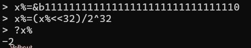 Edited 2025-07-09 19:55 by Volhout PicomiteVGA PETSCII ROBOTS |
||||
| Page 1 of 2 |
|||||
| The Back Shed's forum code is written, and hosted, in Australia. | © JAQ Software 2026 |
