Notice. New forum software under development. It's going to miss a few functions and look a bit ugly for a while, but I'm working on it full time now as the old forum was too unstable. Couple days, all good. If you notice any issues, please contact me.
KiwiJohn Guru Joined: 01/12/2005 Location: New ZealandPosts: 691
Posted: 05:41am 15 Oct 2007
Copy link to clipboard
Print this post
Regarding improved efficiency through various means...
I expect there is an optimum angle for the wind relative to the turbine blade and whenever this angle is not optimum the turbine is either under or over loaded.
Now having thought of this I dont have a clue about how this theory can be practically used.
One idea may be to design a variable pitch system where the pitch is changed automatically in response to relative wind angle.
GWatPE Senior Member Joined: 01/09/2006 Location: AustraliaPosts: 2127
Posted: 01:01pm 15 Oct 2007
Copy link to clipboard
Print this post
Hi KiwiJohn,
One would assume that the design of the mill would give a rotor disk angle of 90 degrees to the wind in normal operation. The only time the rotor disk angle would decrease is when the mill is in furl and overloaded. [assuming this is a side furl design] ie one is attempting to reduce the load on the generator by furling at higher wind speeds. MPPTing is not required once a mill is in this condition.
Any mechanical pitch varying system would have to be tuned, in operation. I cannot see a simple solution to achieving this.
hope this is useful to you, Gordon.become more energy aware
Gill Senior Member Joined: 11/11/2006 Location: AustraliaPosts: 669
Posted: 01:54pm 15 Oct 2007
Copy link to clipboard
Print this post
Quite so John.
With MPPT's or multi coil turn stators or phase switching all these techniques can only improve the conversion of shaft power to electrical power. Sure these approaches greatly improve the electrical efficiency over the range of RPM which equates to varying wind velocity, it does not however address the inefficiencies of fixed props converting wind power to shaft power over the range of speeds usable for power generation.
In the past many attempts have been made to adjust the prop to maintain the correct angle of attack at any speed. The usual method is to employ centrifugal force(increases with RPM) as the force to move and the control indicator. Many mechanisms have been invented but the lack of any in common use is indicative of their high cost and/or ineffectiveness.
Perhaps with the electrical boffins working hard on creating higher electrical efficiencies it is appropriate for the mechanical fraternity to challenge itself with the creation of what is primarily a mechanical system????
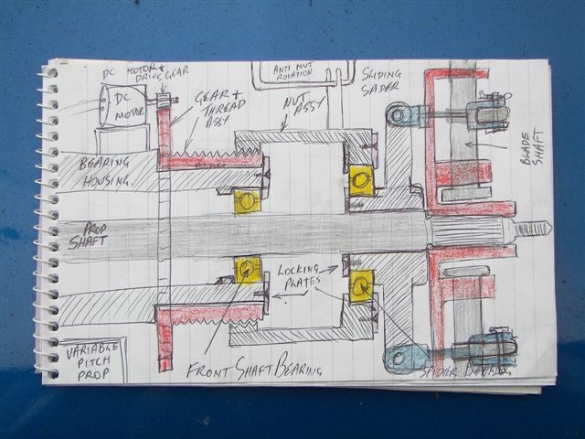
Unfortunately I lack the resources to create and make my own ideas in steel. So here is a sketch of what I would do if I had the resources. Perhaps it will inspire someone with mechanical ability to come up with something "that works".
As you can see I've departed from the centrifugal force method to an electrical/electronic one.(stepping outside the everyone's done it box) The electrical control is not the problem, it is the mechanism.
Yes it does consume the valuable energy that we are trying to create, thats a minus. But on the positive side, besides controlling the angle of attack over the entire power range, it also controls the prop outside that range. It maximizes start up torque by setting the best angle, it feathers the prop when the prop over speeds and it can also brake the prop should an emergency arise. So no more need for furling tails. And all this can be controlled and adjusted from the ground. "I want one".
Well thats my idea.
Anyone else got any?
And as important.... can you build it???Edited by Gill 2007-10-17was working fine... til the smoke got out.
Cheers Gill _Cairns, FNQ
KiwiJohn Guru Joined: 01/12/2005 Location: New ZealandPosts: 691
Posted: 05:01pm 15 Oct 2007
Copy link to clipboard
Print this post
Gordon, sorry I did not express my idea very well. I am of course thinking of wind angle relative to the blade, not the entire rotor disk. However you did touch on something else and that is the lag involved in aligning the rotor as wind direction varies, another possible area of improvement maybe?
Gill, the variable pitch mechanism on some helicopter tail rotors is quite simple(and not really unlike your drawing) though there is just a push rod and a thrust bearing where you have the motor and threaded assembly.
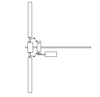
Meanwhile I have been trying to think of something more simple:
In this picture the shaft is at the bottom and one blade is mounted so that it can freely swivel around the 'spoke' that we see extending upwards from the hub. Over to the right is a trim tab mounted on extension arms to get adequate leverage.
The blade is pivoted as near as possible to its centre of pressure, though that may move a bit.
The idea is that in a light wind condition the trim tab will be blown back and the blades will be in fully fine position. As the rotor begins to turn the wind relative to the trim tabs will change and so will the pitch of the main blade, becoming more coarse as RPM increases.
Now I just need to figure out if this is what we want to happen under various conditions.
Warpspeed Guru Joined: 09/08/2007 Location: AustraliaPosts: 4406
Posted: 10:56pm 15 Oct 2007
Copy link to clipboard
Print this post
John, there certainly are correct curvatures and angles, but unfortunately these change along the length of the blade and for different wind speeds.
To gain a bit more insight, try sniffing out some information on sailing, and learn how a yacht sets and trims it's sails. Other sources of information are available from the basic aircraft principles of lift and drag.
Another application might be the blade design of impulse steam turbines in some thermodynamics books, if you are really that interested. The internet is your friend.
What you might need to do is build a wind tunnel and test some scale models of various blade designs. That may not be as impractical as you think.
I have a 3Hp air bower here that I assembled myself, it can generate 110 Kmh maximum airspeed and around 8,000 CFM of flow. This type of centrifugal blower occasionally turns up on e-bay at very reasonable cost. A home made wind tunnel would not be too difficult to make to do some fairly serous testing.
http://i144.photobucket.com/albums/r166/Warpspeed_photos/000 15.jpg
http://i144.photobucket.com/albums/r166/Warpspeed_photos/000 01.jpgEdited by Warpspeed 2007-10-17Cheers, �Tony.
Warpspeed Guru Joined: 09/08/2007 Location: AustraliaPosts: 4406
Posted: 11:18pm 15 Oct 2007
Copy link to clipboard
Print this post
Oooohh!! I like it.
Many World War Two aircraft used variable pitch propellers that used electric motors mounted in the prop hub itself. The motor travels round and round with the hub, and used slip rings for the electrical supply.
Perhaps a small electric motor with an attached very high ratio gearbox, and some fairly simple bell crank linkages mounted on the hub, could move the blades? That may require less precision fabrication ?
This is not really appropriate for us, but out of interest, here is some information on how this worked in the older aircraft:
http://www.k7nv.com/notebook/ppinfo/Cheers, �Tony.
KiwiJohn Guru Joined: 01/12/2005 Location: New ZealandPosts: 691
Posted: 05:06am 16 Oct 2007
Copy link to clipboard
Print this post
Tony, prop driven aircraft, except the smaller ones, still use variable pitch props though I think the modern practice is to have a hydraulic link rather than electric motors to turn the prop blades.
Now, back to the thought provoker I started with.
Tony you are quite right that the blade is twisted and had I been better with the drawing skills it would have appeared twisted!
Though there is no reason why you should know this I do have some basic knowledge of simple aerodynamic principles, two of us did once sail a 32' sloop across the Pacific so I have had a bit of exposure to the principles of sailing too. But none of this really matters and I am not an expert in either field.
Thinking further it would appear that even a variable pitch turbine would be a compromise which leads me to suggest that the best blade would be a flexible one. A blade that actually changes shape to meet varied wind and load conditions. These too factors come together to give the relative angle between the blade and the air flow. Near the root this flow is parallel to the turbine shaft but out near the tips, depending on the speed of the turbine, the angle is much different.
Maybe blades could be made of material, (fibreglass maybe) that would allow the blades to twist at the tip end. This twisting force would come from some sort of vane attached to the tip.
Warpspeed Guru Joined: 09/08/2007 Location: AustraliaPosts: 4406
Posted: 05:34am 16 Oct 2007
Copy link to clipboard
Print this post
Hydraulics have come a long way in sixty years, that is for sure.
I just wished to make the suggestion that mounting a small motor and gearbox right on the hub itself, might produce a simpler mechanical linkage to the blades.
Being able to feather the blades completely in a storm, may be a worthwhile extra feature of variable pitch.
While centrifugal activated, or flexible blades may be practical to build, achieving optimum performance that way might be a lot more difficult. Active motor powered variable pitch could be hooked up as part of an MPPT system, and the whole thing dynamically tuned while in actual operation.
I have never tried anything like this myself, just speculating.Cheers, �Tony.
KiwiJohn Guru Joined: 01/12/2005 Location: New ZealandPosts: 691
Posted: 06:19am 16 Oct 2007
Copy link to clipboard
Print this post
Something that might be practical with the machine shops in one's local town would be to drill the turbine shaft and operate a variable pitch mechanism via a push rod actuated electrically from the 'back' of the alternator. This would be a very simple mechanism but would require the shaft to be hollow.
My original concept of the trim tab to move the blade would fully feather during a storm.
Like you Tony, just speculating.
At the end of the day if I ever get to build anything I will be trying to make it sturdy enough to survive whatever might be thrown at it, obviously with a huge loss of efficiency but that might be the price to be paid.Edited by KiwiJohn 2007-10-17
Gill Senior Member Joined: 11/11/2006 Location: AustraliaPosts: 669
Posted: 11:57am 16 Oct 2007
Copy link to clipboard
Print this post
Mounting a motor in the prop hub was an idea I considered too. Had thought to use a radio link to talk from the fixed picaxe to the spinning picaxe in the prop hub. Struck a problem in accessing power to run it. Considered slip rings but all started to get a bit to complex for a small wind gen.
The prop hub mounted motor is still the best option for dual rotor mills yet we still have the problem of getting power to it past the rotor. A hole down the shaft doesn't help as we end up on the wrong side of the rear rotor and no better off. I just can't see a way of supplying power to the prop of a dual rotor mill.was working fine... til the smoke got out.
Cheers Gill _Cairns, FNQ
KiwiJohn Guru Joined: 01/12/2005 Location: New ZealandPosts: 691
Posted: 06:47pm 16 Oct 2007
Copy link to clipboard
Print this post
The hole down the middle idea was for a push rod to engage with prop blade linkages.
One way of transferring mechanical effort to the blades, using something already at hand, would be to use an adaptation of a car clutch fork and thrust bearing.
If you want to use a radio link and have the entire control system rotating with the prop here are a couple of ideas. Mount a F&P right on the back of the hub with the coil part the rotor (fixed to the prop hub) and the stator drum anchored to the windmill body, cut out nearly all the coil segments leaving just enough to power your system. Another idea, mount an alternator on the front of the hub with its rotor driven by a small prop of opposite pitch to the main rotor (could be noisy though), do the same thing but instead of the contra rotating prop just anchor the stator to a pendulum.
OK, some of those are pretty silly ideas but at least they show it would not be impossible to mount the control gear right on the prop.
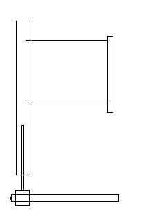
Meanwhile, here is my concept for the most simple variable prop system, I trust the diagram is self explanatory. Uses a clutch thrust bearing etc.
Warpspeed Guru Joined: 09/08/2007 Location: AustraliaPosts: 4406
Posted: 09:03pm 16 Oct 2007
Copy link to clipboard
Print this post
I like the clutch bearing idea John. Helicopter blades are controlled in a fairly similar way to this.
Main rotor:
Tail rotor:
Getting some power to a very small dc motor should not be too difficult. One or two very conventional and very simple brass slip rings should work.
Edited by Warpspeed 2007-10-18Cheers, �Tony.
Gill Senior Member Joined: 11/11/2006 Location: AustraliaPosts: 669
Posted: 01:58am 17 Oct 2007
Copy link to clipboard
Print this post
I've sorted the problem.
"Where there's a Gill there's a Way"
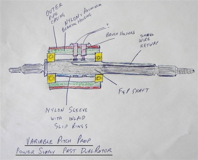
The way past both spinning rotors is not via a hole down the guts but via a keyway down the outside of the shaft.
It need not even be machined. A cut off disc in the right hands could make it.
I think I can retro fit this to my mill in progress.
Now to source the bitz.was working fine... til the smoke got out.
Cheers Gill _Cairns, FNQ
KiwiJohn Guru Joined: 01/12/2005 Location: New ZealandPosts: 691
Posted: 05:37am 17 Oct 2007
Copy link to clipboard
Print this post
I still cant quite drop the idea that the air flow angle relative to the blade is worth further cogitation.
Really what we want is for the finest pitch we can get before the blades start to "stall". (Thats my opinion, feel free to correct me if you know better )
The stall warning on some aircraft is a small vent near the leading edge, as the aircraft wing approaches stall the negative pressure area moves forward from some point on the top of the wing. When this low pressure area crosses the vent the alarm sounds, in some aircraft this is a pressure switch that sounds a horn or buzzer while on others (some light aircraft) the change of pressure causes air to flow though a little reed squeaker thing.
Fortunately, being experienced washing machine knackers we know exactly where to get a quite sensitive pressure switch, dont we?
Other systems use a little tab which is hinged and connected to a switch, in normal mode the tab is one way but when a stall condition occurs the tab is blown the other way and actuates the switch to sound the alarm.
I suggest it may be well worth while investigating the principal of the stall warning sensors for use as an input to a variable pitch control system.Edited by KiwiJohn 2007-10-18
Gill Senior Member Joined: 11/11/2006 Location: AustraliaPosts: 669
Posted: 01:54pm 17 Oct 2007
Copy link to clipboard
Print this post
John, I don't understand what you mean here. At the best it doesn't sound right.
The following is blade theory leading to variable pitch AS I UNDERSTAND IT.
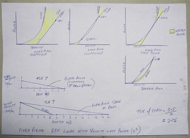
We know wind power is velocity^3 and that generator loading is linear (to a point). We do not need to get into detail provided understanding is maintained.
The 3 top sketches represent common conditions of fixed blade DIY mills.
On the first gen loading is less than power available oft times the owner blissfully ignorant of the wasted power...hay it works fine!
On the second wind power falls short of meeting gen loading. This causes the prop to slow(or not increase speed with increased wind speed) the blades stall usually around 1/3 max expected rpm. The owner curses.
On the third the wind power and gen loading are maximised. There is however large amount of wasted wind power at the higher velocities(fixed pitch & single coil configuration).
With the fourth diagram of that series I see the wind power matching the max gen loading. On a fixed pitch prop that would cause stall at lower rpm. But by varying the pitch to the TSR the blade does not stall with it's resultant loss of lift. When the blade angle changes to match the TSR the Angle of Attack does not increase to stall angle. The Tip Speed is not held linear to wind velocity but adjusts itself to the power available.
From memory
Typical AofA for stall = 16deg
Typical max lift AofA = 12deg
Typical design AofA = 3 - 5deg
I think the stall indicators would be more for warning of pilot error than as efficient flight indicators. I think there may be better ways to indicate pitch adjustment on a wind mill, still I guess it's possible. Edited by Gill 2007-10-18was working fine... til the smoke got out.
Cheers Gill _Cairns, FNQ
KiwiJohn Guru Joined: 01/12/2005 Location: New ZealandPosts: 691
Posted: 05:37pm 17 Oct 2007
Copy link to clipboard
Print this post
Gill, thank you for you diagrams etc.
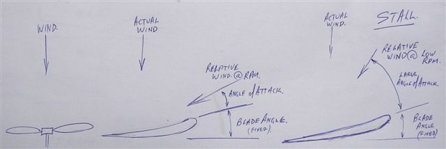
What I am trying to say can be described in the last diagram. In your very last figure you show a blade in stall, it has stalled because either the mill is overloaded and the blade cant turn to make full use of the wind or the wind has suddenly increased, for whatever reason the relative wind vector has moved to cause excessive angle of attack. The blade has stalled and the airflow over the blade is not smooth as we would like it to be causing the low pressure area at the back of the blade to spread out and move nearer to the leading edge which is what the various stall warning sensors would detect.
The blade has stalled because the pitch is too fine for the conditions of load, RPM and wind speed. The blade needs to be moved to a coarser pitch, i.e. move it closer to the relative wind, the RPM will then come up, with the relative wind (and hence angle of attack) moved the blade will be 'flying' again at which point the pitch can be fined a little to extract more power.
So the thing to do in this instance would be to reduce the angle of attack by altering the pitch by twisting the blade in a anti clockwise direction (in your diagram). Do you think this is the right thing to do?
My opening post showed the idea of mounting a moment arm and a vane on each blade to move the blade so as to track optimum angle of attack according to relative wind. No doubt there are more elegant ways involving, for example, some means of detecting relative wind and power driven change of pitch mechanisms, or maybe the moment arm and vane could be used.
I am not batting for the moment arm and vane, what I am doing is trying to stimulate discussion on the importance of angle of attack and ways to detect it make use of the knowledge.
John
Gill Senior Member Joined: 11/11/2006 Location: AustraliaPosts: 669
Posted: 10:44am 18 Oct 2007
Copy link to clipboard
Print this post
Yes John I see where your at.
I agree entirely with what you've said and adding my feeling that if stalled, adjusting the pitch will allow the prop to increase again in speed (in a lower gear as it were).
I'll be honest with you, I'm not to fussed on any physical/mechanical methods of detecting and controlling pitch. If it has reached stall then your detection and correction is to late. The maths required to get those sort of things right is way to involved for me.
My approach would be to run the mill with operational loads and peak the output noting the settings. Write them into the programme, then it doesn't matter what the progression is be it linear, logarithmic, whatever. I don't see the load changing by any significant amount but maybe you have a new variable load application in mind???was working fine... til the smoke got out.
Cheers Gill _Cairns, FNQ
KiwiJohn Guru Joined: 01/12/2005 Location: New ZealandPosts: 691
Posted: 05:58pm 18 Oct 2007
Copy link to clipboard
Print this post
Gill, the first indicator of an approaching stall condition will be the change in relative wind. The quickest way to detect that is with a vane that is moving with the blade. Another would be with a combination of anemometer and RPM, unless you use a sonic anemometer there will be delays in detecting wind speed and direction changes. What we are really interested in is keeping the relative wind angle optimum for the conditions and detecting the onset of a stall does that directly.
I share your reluctance to use physical and mechanical systems if a chip can do the job but sometimes the advantages are obvious, for example I trust you are not thinking of ditching your tail vane and auto furling geometry?
Getting back to keep it simple principles, it occurs to me that the root of the blade does not need to move much and that the relative wind can be most readily sensed at the tip. This leads me to not abandon the principle of a flexible (in the torsional direction) blade that fitted with a pitch controlling vane at the tip, sounds weird but I have a few ideas bubbling around in there.
On another, related, subject. I have a scheme for a sonic anemometer using a PC sound card. I worked this out years ago and just need to revise my recollection of it.
Gill Senior Member Joined: 11/11/2006 Location: AustraliaPosts: 669
Posted: 01:26am 19 Oct 2007
Copy link to clipboard
Print this post
Combining my electrical adjuster with your auto sensing of Angle of Attack, how about a fixed card or vane that faces directly into the relative wind (Blade Angle + AofA)the card has two holes on either side with tubes attached. The tubes go to the hub where they connect to either side of a diaphragm(modified washing machine type?). Note: The static pressures are not measured but used to give a differential(Hi verses Lo) movement in the diaphragm. This movement switches either micro switches of if pressure differences very fine and insufficient, then maybe mercury or reed switches. Then on to electric motor correction.
Best feature:
No moving parts outside of hub.
Tubes run inside existing hollow blades eg. Chinese Al.
Hay! It's just another idea. Edited by Gill 2007-10-20was working fine... til the smoke got out.
Cheers Gill _Cairns, FNQ
KiwiJohn Guru Joined: 01/12/2005 Location: New ZealandPosts: 691
Posted: 05:45am 19 Oct 2007
Copy link to clipboard
Print this post
Crikey Gill, you just invented a stall warning sensor!
It is great to discuss these ideas but at the end of the day I think we can get the same advantages by just making our blades a little longer..
Page 1 of 2
Print this page
The Back Shed's forum code is written, and hosted, in Australia.